Download
1 / 15
150 likes | 330 Vues
Ivo Pol á k, Ji ří Kvasnička polaki@fzu.cz , kvas @fzu.cz QMB6 performance with HBU0, saturation of SiPM Toroidal inductor at PCB Notched fibre light distribution systems 3x24 Conclusions. LED notched fibre distributing system Calibration system for SiPM. QMB6 performance on HBU0. Outline

E N D
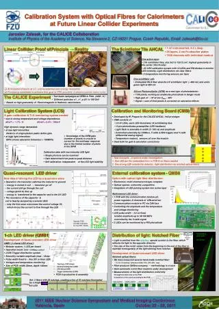
Ivo Polák, Jiří Kvasnička polaki@fzu.cz, kvas@fzu.cz QMB6 performance with HBU0, saturation of SiPM Toroidal inductor at PCB Notched fibre light distribution systems 3x24 Conclusions LED notched fibre distributing systemCalibration system for SiPM Ivo Polák, FZU, Prague
QMB6 performance on HBU0 Outline • SinglePE in HG • Amplitude scans at LG • HG vs LG ratio measurement • 1st correction of ASIC gain • Optical power measured in Prague • 2nd correction of output optical power Jiří Kvasnička, FZÚ, Prague
Single PE spectrum ASIC1 • HG mode, 100fF feedback capacitance • Statistics of 50K events • Big spread of single_photon_peak distance [ADC count / pixel] among the channels • SiPM voltage settings? ASIC0 Fibre end Jiří Kvasnička, FZÚ, Prague
Amplitude scan • Scan at LG, 400fF • ASIC should not be saturated (range up to 4095 bins) Jiří Kvasnička, FZÚ, Prague
HG vs LG radio measurements Old data 29/4/2010 • 1st measurements were measured only in one fixed amplitude. These data were presented in April. Analysis showed, that some channels were saturated in HG mode. • Therefore: we scanned the ratio in several (optical) amplitudes • Data were taken at amplitudes, where • Signal is not saturated in HG mode • Signal is still reasonably high in LG mode • Can the radio be measured by charge injection? How does it correspond? • Pedestal shifts during measurements? Jiří Kvasnička, FZÚ, Prague
Amplitude scan corrected (1) • From the distance between single photon peaks and from the HG vs. LG ratio, we are able to estimate the number of fired pixels • New recalculation: • delivered optical power from the fibre is much more consistent • Curves are less crossing each other • Next step: convert V1 value to optical power (energy) Presented 29/4/2010 Recalculated gain Jiří Kvasnička, FZÚ, Prague
Optical performance at Prague lab • Equipment: Thorlabs PM100D & S130VC • Slope is not linear, especially at very low amplitudes • Reason: energy is stored in the inductor and the peak voltage has to rise above the V2 and the voltage drop of the UV LED 5mm LED 3mm LED Jiří Kvasnička, FZÚ, Prague
Amplitude scan corrected (2) • Linear extrapolation of the initial slope indicate the dynamic range of ~200 MIPs Final comments: • The estimated number of fired pixels is larger than the real number of SiPM pixels • Different shapes of saturation curve might indicate improper HG vs LG ratio • Saturation curves does not match simplef(x)=1-exp(-x) function (unsuccessful fits) • Not yet analyzed: shifts among ASIC memory cells (pedestal and data), crosstalk among memory cells, crosstalk among channels Jiří Kvasnička, FZÚ, Prague
Test mechanical dimension, thickness of PCB on inductance test GND-plane influence Test PCBs with toroidal inductor 60 x 30 mm^2 30 x 60 mm^2 4 layers 3 PCB thicknesses: 0.8, 1.2, 1.8, 3.2mm Collaboration Meeting 11 turns 9 turns Ivo Polák, FZU, Prague
Top layer,pads at right are for smd capacitors 1. First to measure resonant frequency of parasitic capacitors, only. 2. To get value of L, we add larger parallel C, all 200pF with tolerance 1%, And measure the resonance frequency by GDO meter. L C C After recalculating, we can see a spread of L and parasitic C (effect of GND layer) GDO = Grid Dip Meter, handy instrument to measure resonant frequency of LC circuit Ivo Polák, FZU, Prague
Table of inductance values in MHz Test setup is proven, but precise frequency meter (counter) is needed. Internal counter of scope TDS 2024 is the weak point. We will repeat the measurement to satisfy the precision. Ivo Polák, FZU, Prague
Intermediate solution for LED light distribution 2 HBUs = 1 fibre with 24 notches 3 fibres receive light from 1 LED HBU1 HBU2 HBU3 HBU4 HBU5 HBU6 Full length plane = 72 tiles in row Production of 1 fibre with 72 notches is tedious and expensive Agreement reached: 3 parallel fibres, each 24 notches (2 HBUs) For final calo we still plan to use full length fibre with 72 notches – automation needed Ivo Polák, FZU, Prague
Conclusion • We generate optical pulse 250mip equivalent, from single tap • PCB toroidal inductors partly tested, redo with precise counter • An analyze is ongoing • Preparing intermediate solution of layout: 3 fibres by 24 notches Ivo Polák, FZU, Prague
BACK-UP Ivo Polák, FZU, Prague
Backup: Multi-peaks of non-tuned LEDs • “steps” in DNL graph corespond to secondary peaks. These peaks are unwanted, because they make optical pulse longer. • Reason: incorectly damped resonance of QRLED driver Jiří Kvasnička, FZÚ, Prague