Download
1 / 20
250 likes | 386 Vues
Explore a cutting-edge laser calibration method for particle tracking in sPHENIX TPC, benefiting from laser beams to simulate controlled particle tracks and ensuring precise energy deposits with no scattering. Challenge common TPC issues and enhance measurements with laser beam data.

E N D
Laser Calibration System for sPHENIX TPC B.Azmoun, BNL
Laser beams as a Calibration tool • Objective: Use 266nm laser (4.66eV) to liberate charge along beam trajectory to simulate controlled particle tracks in TPC (long history for using laser beams in gaseous detectors) • Features • 2-photon process excites trace organic molecules (~ppb) in gas with ~5-8eV ionization potential (working gas ionization potentials are typically >10eV) • 1-20mJ/mm2 required to liberate an amount of charge equivalent to mip • Ionization clusters are distributed randomly along the track left by the laser beam as they are for an ionizing particle • Ionization yield ~square of laser intensity • Example: 1mm beam s ~400mminduced ionization trail s =400mm/sqrt(2)=280mm. • Smearing in z direction due to length of pulse: for 5ns pulse with uniform distr. s =5ns*vd/sqrt(12) ~ tens of mm • Metals have work functions comparable to 4eV, so most metal surfaces will also liberate electrons if illuminated • Charge is always deposited in a perfectly straight line • Ionization trail from laser simulates infinite momentum particle with zero bend in B-field • Position of beam can be determined beforehand to high precision • Predictable energy deposit, no multiple scattering • Laser can be triggered (and interspersed between physics events) Ref. H.J. Hilke, “Detector Calibration with Lasers” B.Azmoun, BNL
TPC related challenges • Challenges of operating a TPC • High multiplicity environments produce space charge from the primary energy deposit and due to IBF from charge multiplication at the readout (which typically generate orders of magnitude more ions) • Temporal and spatial variations of the drift velocity can be due to variations of ambient conditions: temperature, pressure, E-field distortions from space charge, gas impurities, but gas mixture variations at the level of several percent usually have the largest impact on drift velocity • Intrinsic E-field non-uniformity of field cage (usually controlled to a high level) • Mechanical misalignment of TPC field cage in B-field, resulting in ExB effect • Endcap wheel displacement/inclination wrt to drift field • Impact on TPC measurements • There are many modes for distorting the normal path of an electron in a uniform field, which can severely affect track reconstruction the challenge is to quantify the magnitude of these distortions and remove them • Example of how laser might help: • Momentum resolution is defined by accuracy in sagitta measurement and multiple scattering • For high momentum particles (where MS is negligible), the error in the sagitta is the width of the inverse momentum distribution for radial laser tracks (ALICE) • pid: not so much for sPHENIX B.Azmoun, BNL
Calibration Tools • Benefits of laser beam data • Map out E-field non-uniformities • Map drift velocities throughout TPC volume • Allow corrections for space charge distortions (devise a method that exploits the “straightness” of laser tracks, whose position is known to high precision) • Allow for ExB corrections • Offline correction for mechanical alignment (field cage wrt r/o plane, sector-to-sector alignment) • Debug errors in tracking code • Identify wrong cabling/mapping and non-functioning electronics • Gain monitoring • Monitor transverse (maybe longitudinal) diffusion • Check clock frequency by matching membrane image for both TPC halves • Requirements • Laser beams should sample enough of the drift volume to be able to adequately map out the uniformity in the drift velocity, the distortions in the drift field and check ExB corrections, etc. • Need enough beams to cross all sectors (for sector to sector alignment), with an adequately long track segment over each sector, and with enough time hits along drift (z) • Electron density along laser beam should be higher than the surrounding charge due to the passage of high energy particles • The stability, accuracy, and precision of the laser beam position must be below the required resolution for track reconstruction B.Azmoun, BNL
Schedule of Calibration measurements B.Azmoun, BNL
STAR laser calibration system • Use 4th harmonic of 1064nm laser (266nm), 130mJ/3-5ns pulse Nd-YAG at 10Hz repetition rate, Q-switched (transition from square to Gaussian profile at 20-40m) • Laser head placed outside of magnetic field, use intricate conduit system with optical elements to steer beam to TPC volume • Telescope used to expand beam size to ~25mm • Wide beam split by bundles of 7 micro-mirrors ~1mm diam. • Mirror bundle: quartz fibers with ends cut at 45deg. polished and coated for optimal reflectivity at 266nm (6 fibers arranged hexagonally + 1 in middle) 20-40mJ/pulse (up to 40mJ/mm2) • Planes of 42 laser beam patterns along Z, 30cm apart • 6 planes per TPC half (252 laser beams) used to flood TPC volume to map distortions and measure drift velocity • Produce Poisson “beam” for alignment procedure • Drift velocity measurements to within ~0.02% accuracy • Require 200mm res. in sagitta measurement • Require under 1mm resolution for Z-position • 200mm accuracy for mirror positions • Survey position of mirrors used to define laser beam track • Systematic error checked by comparing identical data from two TPC halves: R=0.99999134+/-0.000225 • Laser beam track stability: ~64mm(10 mip), ~150-200mm(1-2mip) B.Azmoun, BNL
ALICE laser calibration system • Laser beam distribution system is similar to STAR • 336 laser beams, 1mm diam. each (6 laser rods x 4 mirror bundles/rod x 7 beams/bundle x 2 TPC halves) 42 beams per laser beam plane • Organize laser beams into planes at const. z since it is better to measure drift velocity using tracks with ~constant drift times and perpendicular to wires (overall smallest clusters for providing best single point resolution) [this is less complicated than using inclined tracks, but not necessary for sPHENIX] • Strategically placed beams cross over neighboring sectors, avoid beam crossings, flood all sectors and provide 4 discrete z samples optimized for sector alignment and for measuring distortions in the drift velocity • Use the end-plates for absolute reference • Photoelectric effect at central membrane and the readout plane define the absolute start and end point of the drift length B.Azmoun, BNL
Requirements on precision of ALICE laser system • TPC drift field uniformity relative error: within 10-4 • TPC spatial res.: 150mm (r-phi), 200mm(z) • Must ensure matching precision for calibration tracks: • Position of laser must be known to a precision of <100mm (x,y,z) and <0.05-0.1mrad for polar and azimuthal angles (from survey of laser beams during construction) • Reproducibility (stability of beam position): 100mm • Placement of micro-mirrors is the most important factor for determining the precision of the laser beam position • 2nd most important alignment is the angle of the wide beam relative to the mirror bundles B.Azmoun, BNL
ILC Prototype TPC Laser calibration system • Rely on pattern of small Al dots (not lines) on membrane to carry information (integrated along full drift) about distortions on small volume element • No Z-information, however this may be Ok for relatively small TPC’s with short drift lengths, where space charge is not as big an issue Array of Al dots Diffuse laser light Reconstructed position after drift, which integrates all distortions and misalignments B.Azmoun, BNL
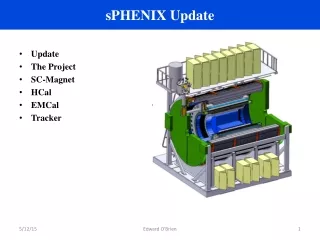
Proposed sPHENIX Laser System • The overall calibration strategy is similar to STAR and ALICE since we plan to shoot laser beams into the TPC drift volume, however there are constraints that must be taken into consideration • DESIGN CONSTRAINTS • No radial space available along barrel for laser beam distr. system driven by TPC momentum spec. (ie, maximizing number of layers leaves little space between TPC and EMCal) • Only input ports available are on endcap (12 outer + 12 inner)planes of laser tracks not possible (ala STAR and ALICE), but angled tracks are • Also, can diffusely illuminate central membrane from endcap ala STAR and ILC TPC • Since there is also little room for a beam conduit system at the endcaps, multiple (relatively small) lasers must be used, each in close proximity to the laser ports at the endcap • Relatively small Diode-Pumped Solid State, Nd:YAG (Q-switched) 266nm Lasers are available (1-6mJ/<1ns pulse) • Beam splitter will require development: how many stable split beams can be established at each TPC port? DPSS Laser/ Beam splitter B.Azmoun, BNL
Preliminary Laser System Concept • STRATEGY • Shine diffuse light onto membrane to liberate small clusters of charge • Pattern on central membrane shall be dots (ala ILC) not lines (ala STAR), as lines only allow space charge distortion determinations perpendicular to the lines dots provide for more info. • Shoot laser beams into TPC volume to mimic particle tracks • Strategically place beams so that each sector will have at least one laser track above it and 2 time hit ranges Charge Cluster from photoelectric effect Charge Cluster from gas ionization At least three varieties of laser sources: Diffuse laser targeting central membrane. Laser going from R=60cm to R=20cm Laser going from R=40cm to R=80cm B.Azmoun, BNL
Benefits of this constrained design • Instead of uniformly flooding the drift volume with laser beams, use guidance from simulations to shoot beams where they are needed most; ie, in areas where we expect high levels of distortion in drift velocity, in space charge, in E-field non-uniformities, and in areas where there is the greatest uncertainty in these parameters • Laser and beam mechanics are directly mounted to endplate, which is effectively a good optical bench, resulting is minimal mechanical drift • The optical system at each laser port is small, relatively simple and decoupled from other ports, which simplifies the alignment procedure • No complex, long chain of optical elements required to be kept in alignment • Since the required track resolution for the TPC is ~150mm, the beam position must be known to a precision better than ~150mm. Ultimately the envisioned beam mechanics for the sPHENIX TPC laser system should be more stable than that of STAR and ALICE, while the requirements for beam position accuracy and precision are comparable. • Laser beams continuously sample all of Z at varying angles (more complicated analysis, but provides a rich data set) • Possibly can introduce trace additives that have a negligible effect on TPC performance, but will increase rate of ionization at lower beam energy density (if laser power becomes an issue) • Possibility to measure/monitor diffusion via photoelectric effect on small dots on membrane B.Azmoun, BNL
Added benefits of this TPC design • IBF can be suppressed significantly in sPHENIX TPC • Gating grid: optimized mesh structure or alternating potential wire plane interrupts path of ions (low diffusion) into drift volume by ~100%, while allowing electrons (high diffusion) through with ~100% transparency (R&D ongoing) • Optimize gap field configurations of MPGD r/o for minimizing IBF while allowing ~100% electron transparency • New hybrid MPGD: GEM+MM operation allows for more degrees of freedom to control flow of ions • Detailed simulation of expected charge build-up in high multiplicity environment was done at SBU • Space charge mostly builds up at surface of inner field cage (r=20cm), but the fiducial acceptance starts at 30cm require few mm correction compared to 10-20cm correction! • …More??? B.Azmoun, BNL
Naive concept for using laser for space point correction • Space charge correction in ALICE (in a nutshell) • The positions of the measured space points (blue) in the TPC are shifted away from the path of the high energy particle due to space charge and electric field distortions • The ITS+TRD+TOF is used to extrapolate a curved reference track (red) crossing the TPC volume • Skipping over the details, the position of the blue points is corrected by an amount (Dx, Dy) to match the reference track. sPHENIX TPC • From a quick discussion with Carlos… • For sPHENIX, since there are no space points outside of the TPC cannot extrapolate reference track • Therefore, must rely on another reference: straight laser track • Laser tracks can provide a Dx, Dy correction map by constraining simulation results • Challenge: arrange for enough laser beams to adequately sample the TPC volume so that the binning of the map is sufficient to recover the requisite resolution • how many beams needed?? TPC Laser track Measured (Dx, Dy) Applied (Dx, Dy) MVTX Extrap. MVTX to corrected TPC data Use prior knowledge of laser track Apply real-life boundary conditions to simulations B.Azmoun, BNL
Conclusion • The laser system will be helpful to correct track distortions as long as the laser beam position can be known to a precision better than the position resolution of the reconstructed particle tracks and provided that a reliable method which utilizes the laser beams is found to establish a map of correction vectors. • Judging from the experience of ALICE and STAR, we should be able to arrange laser beam tracks within the TPC volume to a precision better than the position resolution of the sPHENIX TPC (150mm), considering we can likely build a very stable optical system on each TPC big wheel. • In addition, we foresee requiring smaller corrections than ALICE and STAR since… • Smaller mechanical distortions due to the smaller size of the field cage • Smaller drift lengths likely correspond to less track distortion • Less space charge • Less IBF from readout due to novel gating grid approach • Ne-based gas also reduces IBF (No constraint on having superb energy resolution since we don’t do pid) • Analyze data starting at r=30cm, but most of the space charge is collected at r-20cm • Less primary space charge due to smaller luminosity (interaction rate) at RHIC than at LHC • Pros/cons of magnetic field strength at sPHENIX compared to at ALICE (less diffusion,…,???) B.Azmoun, BNL
Backup B.Azmoun, BNL
Apparatus to measure laser tracks in the lab Laser Beam Field cage TPC zigzag R/O 2x10mm pads) B.Azmoun, BNL
TPC Test Set Up 32cm Drift Cell HV Feed-thru (60kV) Top Fe55 Source Class IV YAG Laser Photodiode -Trigger Bottom Fe55 Source SS Vacuum Vessel 10x0.3mm pad Readout (24ch.) 24 ch. Readout Electronics B.Azmoun, BNL
Drift Velocity Measurement of Candidate Gases • The PD provides a trigger at the time the • laser produces the cluster of electrons. • The drift time is then measured as the arrival • time of the charge cluster at the readout. HV (~32kV) Lens to Focus laser to a point Photo-ionized gas Electron cluster PD -Trigger Laser Drfit Electrons toward Readout (Triple GEM + preamp/shaper) B.Azmoun, BNL
Charge Attachment Measurement for Candidate Gases • As electron clusters produced by the top Fe55 source • drift toward the readout, they lose charge due to charge • loss mechanisms within the gas. • The amount of lost charge may be measured by taking the ratio of the total charge measured at the readout from the top source (~32cm drift) and the total charge measured from the bottom source (~0cm drift) . HV (~32kV) Top Fe55 x-ray Source Bottom Fe55 x-ray Source Drfit Electrons toward Readout (Triple GEM + preamp/shaper) B.Azmoun, BNL