TPC Laser system
TPC Laser system. Design Review, CERN, 27 January 2003 Børge S. Nielsen, J.J. Gaardhøje, N. Lindegaard and Jørn Westergaard Niels Bohr Institute A. Lebedev, Brookhaven National Laboratory. Functions of the system Basics of the design Construction tolerances and alignment

TPC Laser system
E N D
Presentation Transcript
TPC Laser system Design Review, CERN, 27 January 2003 Børge S. Nielsen, J.J. Gaardhøje, N. Lindegaard and Jørn Westergaard Niels Bohr Institute A. Lebedev, Brookhaven National Laboratory • Functions of the system • Basics of the design • Construction tolerances and alignment • Lab tests at NBI • Status of system components • Production status and installation Børge Svane Nielsen, NBI
Laser system objectives • Electronics testing • Sector alignment • Drift velocity monitoring • Pressure, temperature • Temperature gradients (stratification?) • ExB effects, space charge • Two possible approaches: • Relative measurements, rely only on time stability of laser ray position • Absolute measurements, requires knowledge of absolute position of laser ray. More ambitious Børge Svane Nielsen, NBI
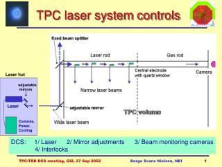
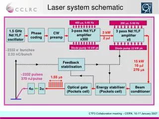
TPC Laser principle 20-40 μJ/pulse, = 1 mm 266 nm, 100 mJ/pulse, 5 ns pulse, = 25 mm Børge Svane Nielsen, NBI
Beam pattern inside TPC Radial beams Stratetic sector boundary crossings Avoid laser beam crossings 8 ’layers’ of rays along z 336 laser tracks in full TPC Børge Svane Nielsen, NBI
UV laser Spectron Laser Systems (UK): model SL805-10-UPG Pulsed UV laser (Nd:YAG): 100 mJ / 5 ns pulse @ 266 nm, max 10 Hz expanded beam = 25 mm divergence < 0.35 mrad, pointing stability < 0.1 mrad remote controllable (RS-232) Børge Svane Nielsen, NBI
Laser hut and laser beam transport (1) Børge Svane Nielsen, NBI
Laser hut and laser beam transport (2) Børge Svane Nielsen, NBI
Beam transport on TPC end plates (1) Shaft side Beam monitor Beam splitter 99/1 Prism 30º bend Beam splitter 50/50 Prism 30º bend Beam splitter 50/50 Beam splitter 33/67 Beam entrance 90º mirror Muon side beam entrance Børge Svane Nielsen, NBI
Beam transport on TPC end plates (2) Muon side Beam monitor Beam splitter 99/1 Prism 30º bend Beam splitter 50/50 Beam splitter 50/50 Beam splitter 33/67 Beam entrance 90º mirror Børge Svane Nielsen, NBI
Muon arm side beam transport limited space between TPC and space frame move beam transport 10º from vertical plane adds 2 mirrors on shaft side + modifies beam transport on muon side Shaft side ”standard” prism ”knee” in beam transport on shaft side Muon side special prism attach 50 mm pipe on outside of TPC permanently We are currently considering to move back into the vertical plane Børge Svane Nielsen, NBI
Optics on TPC end plates Market survey on optical components for end-plates ongoing Design in progress on opto-mechanical supports on end-plates (copy/modify STAR systems): Prism holder Laser beam Construction foreseen in NBI workshop Piezo-electric adjustment system from New Focus on order Børge Svane Nielsen, NBI
Mirror adjusters Based on commercial piezo solution 3 fully adjustable mirrors per half-TPC Ethernet interface Børge Svane Nielsen, NBI
Laser rod with mirrors Børge Svane Nielsen, NBI
Mirror support rings All rings have been produced at NBI Børge Svane Nielsen, NBI
Micro-mirror z positions • 4 micro-mirrors per rod, at about (0, 1/3, 2/3, 1) length • vary z positions slightly between odd (a) and even (b) rods (a) (b) (a) (a) (b) (b) Børge Svane Nielsen, NBI
Alignment by Poisson spot Screen Wide laser beam Ball or disc d Camera = 266 nm Børge Svane Nielsen, NBI
Operational aspects • Sensors and remote controls: • Remote setup and monitoring of laser • CCD cameras for beam positioning: entrance mirrors on end plates end points on end plates end of laser rods • Remote beam manipulation: 4 mirrors in laser hut 1 entrance mirror on each end plate • Data taking: • Test + special calibration runs: trigger from laser trigger laser ( several μs @ 10 Hz) • Normal physics runs: low rate trigger from laser Børge Svane Nielsen, NBI
Stability of laser and beams Design with micro-mirrors laser ray positions determined by the mirror positions and angles, not by the main laser beam or movable optics. Mechanical stability of the TPC is good enough for precise (100 m) relative measurements once the TPC is installed. During construction and installation, the TPC will undergo stresses due to handling (rotation) and change of loads (ROCs, cables etc). ’Absolute’ positions must refer to: TPC end plates, ROCs and Central Electrode. Børge Svane Nielsen, NBI
Construction tolerances and alignment accuracy (1) • What is known precisely and ’absolutely’ during construction? • (100-150 m) • pad plane z and wire z and x/y position • central electrode z position • Well measured relative to each other (100-150 m, 0.05 mrad): • internal dimensions and angles in micro-mirror bundles • micro-mirror bundles in support rings • bundle support rings in uninstalled rods • Less well measured or prone to move during handling • (500 m, 0.2 mrad): • rod positions relative to ROCs, central electrode and ALICE x,y,z Børge Svane Nielsen, NBI
Construction tolerances and alignment accuracy (2) • Additional alignment relative to end plates • with horizontal and loaded TPC • (100-200 m, 0.05 mrad): • measure rod / micro-mirror bundle positions by survey through rods (fiducial marks useful) • measure some beams near inner cylinder with HeNe laser after rod installation • ’Internal alignment’ and iterations (offline analysis) : • electrons from central electrode ’absolute’ z • electrons from ROC pad plane and wires ’absolute’ z, x/y • laser tracks close to outer rods good relative alignment • laser tracks are straight lines • iterate to best ’absolute’ positions of laser rays • track time variations Børge Svane Nielsen, NBI
Status and Tests • Laser lab at NBI • Micro-mirror production in Moscow • Tests of micro-mirrors at NBI • Status of other components Børge Svane Nielsen, NBI
Laser lab at NBI rod with micro-mirrors CCD camera power supply 1064 nm laser amplifier expandingtelescope quadrupler 266 nm doubler 532 nm Børge Svane Nielsen, NBI
Reflected 1 mm beam z=31cm z=200cm FWHM=0.93mm FWHM=0.95mm pure Fresnel diffraction Børge Svane Nielsen, NBI
Reflected 1 mm beams (2) 16 cm 19 cm 23 cm Fresnel diffraction FWHM=1.00mm 1.01mm 1.10mm 31 cm 47 cm 100cm Measured 0.93mm 1.17mm 0.93mm 150cm 200cm z=250 cm beam divergence 0.35 mrad 1.14mm 0.79mm 0.95mm Børge Svane Nielsen, NBI
Micro-mirror production All 60 bundles produced and delivered in September 2002, but problems with surface quality on some mirrors and mechanical precision on some cups preliminary: 46 accepted based on surface quality most of these will be accepted after being mechanically improved at NBI additional 30 bundles almost ready in Moscow mechanical reference surface brass cup reflecting surfaces 1 mm quartz fibres cut at 45º, polished, coated 7 micro-mirrors/bundle Micromirror bundle Børge Svane Nielsen, NBI
Angles measurements (1) and angles of all micromirror faces measured by goniometer in Moscow 0.0014 (5 arc sec) Børge Svane Nielsen, NBI
Angles measurement (2) • Re-calculation of angles to take into • account offset centres of 7 mirrors • systematics in re-calculation still to be understood Børge Svane Nielsen, NBI
Angles measurement (3) • However: • reference surface not good • bundle not fixed to support • in reproducible way • only relative angles any good from this measurement Reference surface has been turned off in NBI workshop to provide good surface Børge Svane Nielsen, NBI
Mirror surfaces (1) Looked at all mirror reflections after 2.5 m. Example: bundle 18+19 Børge Svane Nielsen, NBI
Mirror surfaces (2) Analysed all mirror reflection profiles after 2.5 m. Example: bundle 18+19 Rejected bad reflectivities and image shapes. Good mirrors generally have quite uniform reflectivity Børge Svane Nielsen, NBI
Mirror reflectances Amplitudes of profiles on previous slide: Micro-mirror number Acceptance level: 150 (arbitrary units) Preliminary accepted bundles (based on reflectivity and image quality): 46 bundles out of 61 received Børge Svane Nielsen, NBI
Angles measurements @ NBI (1) All mirror angles have been re-measured at NBI, using laser beam setup. Estimated precision: 0.5 mrad (2 arc min) 0.5 mrad (2 arc min) Børge Svane Nielsen, NBI
Angles measurements @ NBI (2) Børge Svane Nielsen, NBI
Angles measurements @ NBI (3) Mean = -0.08 Sigma = 0.51 Mean = -0.29 Sigma = 0.94 Børge Svane Nielsen, NBI
Linear measurements @ NBI Mean = -0.23 mm Sigma = 0.57 mm L Børge Svane Nielsen, NBI
Rod gluing • Drill holes in short rods • Mount mirror bundles in support rings. • Glue mirror support rings onto short rods. Theta alignment guaranteed by jig + machined surface 4. Glue short rods into full length rods. Phi alignment adjusted during gluing • Measurements on final rod possible before installation. • Foreseen for February-March at CERN. Børge Svane Nielsen, NBI
Production status and installation schedule Rod system: Micro-mirror bundles: ready ~1 Feb 2003 Mirror support rings produced Mirror testing: ongoing, fall 2002 + beginning 2003 Rod production at CERN: spring 2003 Optics system: Principle design: done Detailed design: spring 2003 Production and installation: mid 2003 - spring 2004 Integration: Principle design: done Install laser in UX25: 2005 + 2006 Commissioning: Together with TPC chambers: 2nd half 2004 + 2005 Notes and presentations: http://www.nbi.dk/~borge/tpclaser/ Børge Svane Nielsen, NBI