TPC Laser system
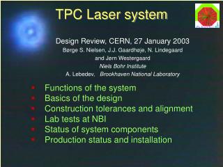
TPC Laser system. Functions of the system Basics of the design Design updates since February TB Lab tests at NBI Construction tolerances and alignment Production status and installation. ALICE Technical Board, CERN, 14 May 2002 Børge S. Nielsen, Jørn Westergaard and J.J. Gaardhøje

TPC Laser system
E N D
Presentation Transcript
TPC Laser system • Functions of the system • Basics of the design • Design updates since February TB • Lab tests at NBI • Construction tolerances and alignment • Production status and installation ALICE Technical Board, CERN, 14 May 2002 Børge S. Nielsen, Jørn Westergaard and J.J. Gaardhøje Niels Bohr Institute A. Lebedev, Brookhaven National Laboratory Børge Svane Nielsen, NBI
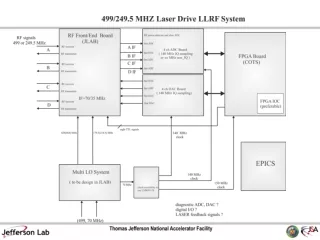
Laser system objectives(P. Glässel, LHCC review) • Electronics testing • Sector alignment • Drift velocity monitoring • Pressure, temperature • Temperature gradients (stratification?) • ExB effects, space charge • Two possible approaches: • Relative measurements, rely only on time stability of laser ray position • Absolute measurements, requires knowledge of absolute position of laser ray. More ambitious Børge Svane Nielsen, NBI
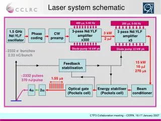
TPC Laser principle 20-40 μJ/pulse, = 1 mm 266 nm, 100 mJ/pulse, = 25 mm Børge Svane Nielsen, NBI
Beam pattern inside TPC Radial beams Stratetic sector boundary crossings Avoid laser beam crossings 336 laser tracks in full TPC Børge Svane Nielsen, NBI
Laser beam transport to TPC Laser beams Shaft side beam Muon side beam Børge Svane Nielsen, NBI
New muon arm side beam transport limited space between TPC and space frame move beam transport 10º from vertical plane adds 2 mirrors on shaft side + modifies beam transport on muon side beam transport as foreseen earlier new layout special prism new placement hope to attach 50 mm pipe on outside of TPC permanently Børge Svane Nielsen, NBI
Beam transport on TPC end plates Muon side Beam monitor Beam splitter 99/1 Prism 30º bend Beam splitter 50/50 Beam splitter 50/50 Beam splitter 33/67 Beam entrance 90º mirror Børge Svane Nielsen, NBI
Optics on TPC end plates Example of optics box on TPC end plate Prism box used in STAR Børge Svane Nielsen, NBI
Micro-mirror production A.Ridiger, Moscow: all fibres cut, polished, coated and tested 43 of 60 mirror bundles produced angle measurements about to start micro-mirror bundle brass cup protection cap 1 mm quartz fibres cut at 45º, polished, coated 7 micro-mirrors/bundle Børge Svane Nielsen, NBI
Laser rod with mirrors drawing shown in February New: Alu ring design changed & mirror support integrated with rings Børge Svane Nielsen, NBI
Mirror support rings New mirror support integrated with Alu rings: Prototype produced at NBI Børge Svane Nielsen, NBI
Micro-mirror z positions • 4 micro-mirrors per rod, at about (0, 1/3, 2/3, 1) length • vary z positions slightly between odd (a) and even (b) rods (a) (b) (a) (a) (b) (b) Børge Svane Nielsen, NBI
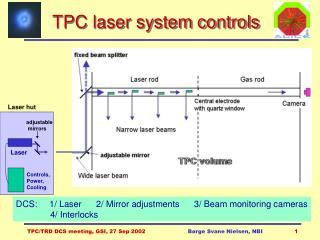
Operations • Sensors and remote controls: • Laser setup and monitoring by RS 232 • CCD cameras for beam positioning: entrance mirrors on end plates end points on end plates end of laser rods • Beam manipulation: few mirrors in laser hut entrance mirrors on end plates • Data taking: • Test + special calibration runs: trigger from laser trigger laser ( several μs @ 10 Hz) • Normal physics runs: low rate trigger from laser Børge Svane Nielsen, NBI
Laser lab at NBI rod with micro-mirrors CCD camera power supply 1064 nm laser amplifier expandingtelescope quadrupler 266 nm doubler 532 nm Børge Svane Nielsen, NBI
Reflected 1 mm beam z=31cm z=200cm FWHM=.93mm FWHM=.95mm Børge Svane Nielsen, NBI
Reflected 1 mm beams (2) 16 cm 19 cm 23 cm Fresnel diffraction FWHM=1.00mm 1.01mm 1.10mm 31 cm 47 cm 100cm Measured 0.93mm 1.17mm 0.93mm 150cm 200cm z=250 cm beam divergence 0.35 mrad 1.14mm 0.79mm 0.95mm Børge Svane Nielsen, NBI
Stability of laser and beams Design with micro-mirrors laser ray positions determined by the mirror positions and angles, not by the main laser beam or movable optics. Mechanical stability of the TPC is good enough for precise (100 m) relative measurements once the TPC is installed. During construction and installation, the TPC will undergo stresses due to handling (rotation) and change of loads (ROCs, cables etc). ’Absolute’ positions must refer to: TPC end plates, ROCs and Central Electrode. Børge Svane Nielsen, NBI
Construction tolerances and alignment accuracy (1) • What is known precisely and ’absolutely’ during construction? • (100-150 m) • pad plane z and wire z and x/y position • central electrode z position • Well measured relative to each other (100-150 m, 0.05 mrad): • internal dimensions and angles in micro-mirror bundles • micro-mirror bundles in support rings • bundle support rings in uninstalled rods • Less well measured or prone to move during handling • (500 m, 0.2 mrad): • rod positions relative to ROCs, central electrode and ALICE x,y,z Børge Svane Nielsen, NBI
Construction tolerances and alignment accuracy (2) • Additional alignment relative to end plates • with horizontal and loaded TPC (dedicated effort) • (100-200 m, 0.05 mrad): • measure rod / micro-mirror bundle positions by special survey through rods (fiducial marks useful) • measure some beams near inner cylinder for beams close to end-plate through holes for IROCs • ’Internal alignment’ and iterations (offline analysis) : • electrons from central electrode ’absolute’ z • electrons from ROC pad plane and wires ’absolute’ z, x/y • laser tracks close to outer rods good relative alignment • laser tracks are straight lines • iterate to best ’absolute’ positions of laser rays • track time variations Børge Svane Nielsen, NBI
Production status and installation schedule Rod system: Micro-mirror bundles in production Mirror support rings designed, needs final approval from TA2 Ring production, mirror installation: summer 2002 Rod production at CERN: fall 2002 Optics system: Principle design: done Detailed design: summer/autumn 2002 Production and installation: 2nd half 2003 + 2004 Commissioning: Together with TPC chambers Draft note: http://www.nbi.dk/~borge/tpclaser/ Børge Svane Nielsen, NBI