Download
1 / 18
180 likes | 300 Vues
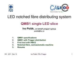
Ivo Pol á k, on behalf prague’s group polaki@fzu.cz QMB1 specifications QMB1 with Trigger distribution First test with HBU2 Notched fibre, semiautomatic machine Resume. LED notched fibre distributing system QMB1 single LED slice. QMB1. Q uasi resonant M ain B oard

E N D
Ivo Polák, on behalf prague’s group polaki@fzu.cz QMB1 specifications QMB1 with Trigger distribution First test with HBU2 Notched fibre, semiautomatic machine Resume LED notched fibre distributing systemQMB1 single LED slice Ivo Polák, FZU, Prague
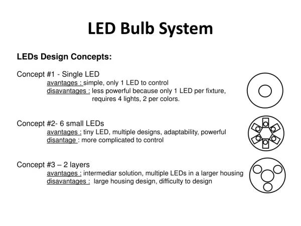
QMB1 • Quasi resonant Main Board • Modular system, 1 LED per board • Operation mode: • DAQ + CANbus control • stand-alone mode • LVDS Trigger distribution system • Variable amplitude, zero to maximum (~1Amp) smooth • Pulse width fixed to ~ 5ns (UV or blue LED) • Voltages and temperature monitoring • Size of PCB: width 30mm, depth 140mm Ivo Polák, FZU, Prague
Principal schema Larger inductor than the older QMB6 Ivo Polák, FZU, Prague
TRIGGER (T-calib) LVDS distribution to QMB1 master slave slave slave slave TX RX Terminated 120ohm Terminated 120ohm LVDS Up to 6 + 6 slaves modules Trigger from DAQ Ivo Polák, FZU, Prague
Signal distribution at 30 x 140 mm^2 Two flat cables, Twisted pair for Trigger Ivo Polák, FZU, Prague
Frame with 5 (and 1 spare) QMB1 Ivo Polák, FZU, Prague
3D draw of QMB1 T-calib LVDS flat cable LED PWR 15V and CANbus fibre Ivo Polák, FZU, Prague
Real single LED board QMB1 Power 15V 60mA High level of LED peaks, 1.7A in pulse Delay can be easily trimmed within 9ns LED pulse width is shorter than expected 2ns, seen with current probe Tested now in stand-alone mode Ivo Polák, FZU, Prague
PIN-PD response to QMB1 flash PIN-PD only, no preamp 5ns/div Upper: PIN-PD w preamp 10ns/div Lower: PIN-PD w preamp 50ns/div Maximal LED amplitude, LED airgap to PIN-PD Ivo Polák, FZU, Prague
DESY test setup in December 2012 HBU2 SPIROC2 Notched fibres Single layer frame PWR 15V DIF, PWR, CAL QMB1 QMB1 QMB1 QMB1 combiner CANbus T-calib from DAQ Ivo Polák, FZU, Prague
DESY test setup in December Only 11 points were illuminated properly Notched fibre (routed in paralel with blue line) Ivo Polák, FZU, Prague
Quick Friday’s QMB1 test with HBU2 System is working! , butBig spread due to combination of factors: Bad fibre, hold scan did not matched • Some config troubles occurred • Generally, system is working easily, run in stand-alone mode • Pulse position at different LEDs can be easy tuned within 1ns • Near future plans (tomorrow) • Hold scan • Better notched fibre to install • Single p.e. peak spectra • Next year plan (February) • More channels equipped with scintillators • Xtalk and light spread study Distribution will be better, do not worry! Ivo Polák, FZU, Prague
Notched fibres illuminated by Green laser 24 notches • external company Safibra preparing the setup (semiautomat) to produce precise notches in the fibres • We assume to have fibres made by new technology in 1.Q 2012, we assume less spread of the light at taps (<15% ). • prototype fibres showed some systematic error (decay) in distribution of light, two test methodes two results: flat and with decay. Under investigation now. Ivo Polák, FZU, Prague
Notched fibresSemi-automatic tool Now in operational debugging & sw development stage Alu/PCB Template with moving scint tile Frame with x-y stepper motors Drill machine used as milling cutter to groove the notch PCB with 3mm holes Scintilator tile w SiPM Ivo Polák, FZU, Prague
QMB1 (1-chanel LED driver): Done 6 pcs of QMB1 in hand Tune QRLed driver to 405nm LED Trigger distribution (LVDS) proved Trigger delay can be tuned by C trimmer (~10ns) A few bugs in circuitry found Still short 3ns pulse To be done: finishing and debugging of fw – CANbus and monitoring Set of notched fibers, semiautomatic machine in tuning procedure Set: 3*fibre with 24 notches, creating a line of 72 notches. 3 sets of fibres will be delivered in 1.Q-2012 work at autumn of 2011 Ivo Polák, FZU, Prague
Resume • QMB1 is in basic operational stage • It is working, no major troubles occurred • First 6 boards (version 1) we have in hand • More work on fw to be done • Upgrade of QMB1(v2.0) is foreseen in mid of 2012 • Notched fibre semiautomatic machine is hw ready, its sw is under development Ivo Polák, FZU, Prague
Distribution of light:Notched Fiber Iluminated by Green laser 24 notches • Light is emitted from the notches • The notchis a special scratch to the fiber, which reflects the light to the opposite direction • The size of the notch varies from the beginning to the end of the fiber to maintain homogeneity of the light, which comes from notches Emission from the fiber (side view) First notch Middle notch End position notch Ivo Polák, FZU, Prague
Mechanical layout of QMB1 LED Outer line: 30 (29) x 140 mm*2 4 mounting holes for M2.5 screw Ivo Polák, FZU, Prague