JET ENGINE MECHANICAL ARRANGEMENT
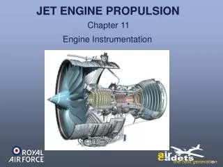
JET ENGINE MECHANICAL ARRANGEMENT. More generally known as ‘ GAS TURBINE ’ Engine. THE WORKING PARTS OF A JET ENGINE. Rolls-Royce AVON – Canberra – 1950’s technology. Fuel, Oil, and Hydraulic Pumps, Electrical Generators, RPM Governor.


JET ENGINE MECHANICAL ARRANGEMENT
E N D
Presentation Transcript
JET ENGINE MECHANICAL ARRANGEMENT More generally known as ‘GAS TURBINE’ Engine THE WORKING PARTS OF A JET ENGINE
Rolls-Royce AVON – Canberra – 1950’s technology
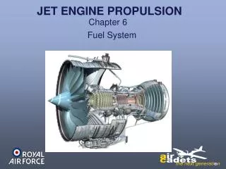
Fuel, Oil, and Hydraulic Pumps, Electrical Generators, RPM Governor. Rolls-Royce AVON - (Graphic Representation) Compressor Handling Bleed Valve Front Engine Mount Rear Compressor Case Combustion Chambers (Cans) Intake Anti-Icing Tube Jet Pipe (Exhaust) Front Compressor Casing Accessory Gearbox Oil Tank Turbine Section Rear Engine Mount
FRONT BULLET AND SUPPORT VANES SUPPORT BEARINGS REAR CONE AND SUPPORT VANES NOZZLE GUIDE VANES (NGV’S) STATOR VANES COMPRESSOR OUTER CASINGS COMBUSTION OUTER CASINGS COMBUSTION INNER CASING COMBUSTION FLAME TUBE Engine Casings – Static Assembly
Compressor Blades Turbine Blades Shaft Assembly Rotating Assembly
2,500 Deg C Above ambient 450 Deg C 1,000 Deg C Ambient temp The shaded area is called the ‘GAS PATH’. These sections expand first Problem! Temperature changes cause the shaft and casings to expand and contract But by different amounts! This could put tremendous unwanted forces on the casings and shaft leading to failures (We’ll look at what happens to the air passing through the GAS PATH in Gas Turbine Operation.) Solution? Its all in the bearings!
Front Bearing Chamber Centre Bearing Chamber Rear Bearing Chamber Roller Bearing Ball Bearing (Location Bearing) Roller Bearing Bearing Chambers
Ball Bearings Provide Positive Axial Location Hot section Casing Shaft Front Bearing Chamber Centre Bearing Chamber Rear Bearing Chamber Casing Representation of jet engine bearing layout
Casing Then, with ‘heat soak’ the shaft expands Casing Shaft and Casing have no differential movement at this point The casing expands first - pushing the rear outer bearing with it The same happens at the front with pressured air and heat sink from the combustor heating the hardware The engine is actually designed to dimensions based on normal operating temperatures Shaft
JET ENGINE COMBUSTOR OPERATION WHERE THE POWER IS PRODUCED
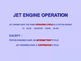
THE COMBUSTION PROCESS IN A PISTON ENGINE: - FUEL IS MIXED WITH AIR BEFORE ENTERING THE CYLINDERS THE FUEL/AIR MIXTURE IS THEN COMPRESSED THEN IT IS IGNITED BY A SPARK ONCE FOR TWO REVS OF THE ENGINE (IN THE 4 STROKE CYCLE) IN A JET ENGINE: - AIR IS COMPRESSED AND FORCED INTO THE COMBUSTOR FIRST THEN THE FUEL IS SPRAYED IN UNDER PRESSURE IT IS THEN IGNITED BY A SPARK (BUT ONLY ONCE FOR STARTING) COMBUSTION IS THEN CONTINUOUS WHILST THE ENGINE IS RUNNING THE SAME AS A PLUMBERS BLOW TORCH!
We’re going to look in detail at what happens here But first we’ll look at the layout of the combustion system
COMBUSTOR LAYOUT – (ALSO HISTORICAL DEVELOPMENT) ENGINE STRUCTURE AND SHAFTS EACH CAN HAS A FUEL SPRAY NOZZLE (FSN) OUTER CASING INNER CASING INDIVIDUAL COMBUSTORS – ‘CANS’ 1st JET ENGINES WHITTLE ETC FLAME CONTAINED WITHIN THIS TUBE ‘FLAME-TUBE’
IGNITERS COMBUSTOR LAYOUT – (ALSO HISTORICAL DEVELOPMENT) CANS CONNECTED TOGETHER TO EQUALISE PRESSURES AND TO SPREAD THE FLAME ON START UP TYPICAL OF DART SERIES TURBO PROPS
INDIVIDUAL CANS WITH INTER-CONNECTORS ANNULAR OUTER CASING IGNITERS COMBUSTOR LAYOUT ‘CAN-ANNULAR’ LAYOUT ALSO FORMS THE ENGINE STRUCTURE TYPICAL OF SPEY &TAY BYPASS ENGINES
ANNULAR OUTER CASING ANNULAR INNER CASING ANNULARLAYOUT COMBUSTOR LAYOUT GIVES EVEN TEMPERATURE FACE TO TURBINE BLADES THE LAYOUT OF CHOICE FOR MODERN BYPASS ENGINES ALLOWS MORE FSN’S TO BE FITTED
THE CROSS SECTION OF ALL THESE LAYOUTS IS VIRTUALLY IDENTICAL AND THEREFORE SO IS THE AIRFLOW!
Outer Combustion Casing 82% Cooling Flow Inner Flame Tube 1st Stage NGV’s 18% Vortex Flow Recirculating Vortex Fuel Feed