Understanding Bipolar Junction Transistors (BJTs): Types, Structure, and Amplification Factors
200 likes | 392 Vues
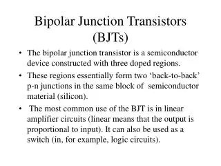
Bipolar Junction Transistors (BJTs) are crucial components in electronic circuits that can amplify current. This guide covers the two main types of BJTs: NPN and PNP, detailing their structures, symbols, and modes of operation. You'll learn about the current flow conventions and the various transistor connections including common base, common collector, and common emitter configurations. Key amplification factors such as α and β, along with their formulas for collector current calculations, are explained to provide a comprehensive understanding of BJTs.

Understanding Bipolar Junction Transistors (BJTs): Types, Structure, and Amplification Factors
E N D
Presentation Transcript
Bipolar Junction Transistors (BJTs) Bipolar Two Polarity Transistor Resistor Tranfer +
Types of BJTs • NPN • PNP
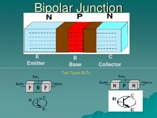
p-type n-type n-type NPN-BJT Structure
C B E NPN BJT Symbol
n-type p-type p-type PNP-BJT Structure
C B E PNP BJT Symbol • Emitter is reversed
E Base (p-type) C Emitter (n-type) Collector (n-type) B Current Flow Convention IE IC IB
BJT structure note: this is a current of electrons (npn case) and so the conventional current flows from collector to emitter.
Transistor Connections • Common Base Connection • Common Collector Connection • Common Emitter Conncetion
Current Amplification Factor α =IC / IE ( constant VCB) • The value of α is lies b/w 0.9 to 0.999 • Total collector current • IC=αIE+Ileakage
Current Amplification Factor • γ = IE/IB • Expression for collector current. • IC= IB /1-α+ ICBO /1-α
Base Current Amplification Factor • β= IC / IB • The range of β is 20 to 500. • Expression for collector current. • IC= βIB + ICEO