Understanding Capacitors: Fundamentals, Functions, and Calculations
This document delves into the fundamental principles of capacitors, including their definition, function, and the relationship between charge and voltage. It covers concepts such as capacitance (C = Q/V), energy storage, and potential difference. Additionally, the content explains how capacitors are connected in series and parallel, highlighting the differences in charge and voltage across these configurations. The document also includes practical examples and calculations, helping students grasp the essential theories and applications of capacitors in electrical circuits.

Understanding Capacitors: Fundamentals, Functions, and Calculations
E N D
Presentation Transcript
CAPACITORS September 29, 2008
How did you do? • Great • OK • Poor • Really bad • I absolutely flunked!
Calendar of the Day • Exams will be returned within a week. • If you did badly in the exam you need to have a plan to succeed. Let me know if you want any help with this. • Quiz on Friday – Potential or Capacitance. • WebAssign will appear shortly if it hasn’t done so already. • There is a WA on board for potential. • Quizzes are in the bin on the third floor through the double doors.
Two +q charges are separated by a distance d. What is the potential at a point midway between the charges on the line connecting them • Zero • Kq/d • Kq/d • 2Kq/d • 4kq/d
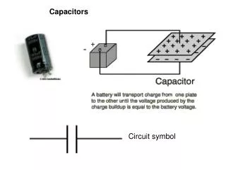
A simple Capacitor • Remove the battery • Charge Remains on the plates. • The battery did WORK to charge the plates • That work can be recovered in the form of electrical energy – Potential Difference TWO PLATES WIRES WIRES Battery
d Air or Vacuum E - Q +Q Symbol Area A V=Potential Difference Two Charged Plates(Neglect Fringing Fields) ADDED CHARGE
Where is the charge? +++++ + - - - - - - d AREA=A s=Q/A Air or Vacuum E - Q +Q Area A V=Potential Difference
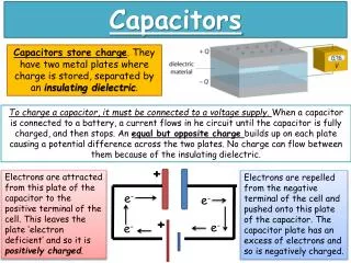
One Way to Charge: • Start with two isolated uncharged plates. • Take electrons and move them from the + to the – plate through the region between. • As the charge builds up, an electric field forms between the plates. • You therefore have to do work against the field as you continue to move charge from one plate to another. The capacitor therefore stores energy!
Capacitor Demo
d Air or Vacuum E - Q +Q Gaussian Surface Area A V=Potential Difference More on Capacitors Same result from other plate!
DEFINITION - Capacity • The Potential Difference is APPLIED by a battery or a circuit. • The charge q on the capacitor is found to be proportional to the applied voltage. • The proportionality constant is C and is referred to as the CAPACITANCE of the device.
UNITS • A capacitor which acquires a charge of 1 coulomb on each plate with the application of one volt is defined to have a capacitance of 1 FARAD • One Farad is one Coulomb/Volt
The two metal objects in the figure have net charges of +79 pC and -79 pC, which result in a 10 V potential difference between them. (a) What is the capacitance of the system? [7.9] pF(b) If the charges are changed to +222 pC and -222 pC, what does the capacitance become? [7.9] pF(c) What does the potential difference become?[28.1] V
NOTE • Work to move a charge from one side of a capacitor to the other is qEd. • Work to move a charge from one side of a capacitor to the other is qV • Thus qV=qEd • E=V/d As before
Continuing… • The capacitance of a parallel plate capacitor depends only on the Area and separation between the plates. • C is dependent only on the geometry of the device!
Simple Capacitor Circuits • Batteries • Apply potential differences • Capacitors • Wires • Wires are METALS. • Continuous strands of wire are all at the same potential. • Separate strands of wire connected to circuit elements may be at DIFFERENT potentials.
Size Matters! • A Random Access Memory stores information on small capacitors which are either charged (bit=1) or uncharged (bit=0). • Voltage across one of these capacitors ie either zero or the power source voltage (5.3 volts in this example). • Typical capacitance is 55 fF (femto=10-15) • Probably less these days! • Question: How many electrons are stored on one of these capacitors in the +1 state?
Cap-II October 1, 2008
Note: • I do not have the grades yet. Probably by Friday. • Quiz on Friday … Potential or Capacitors. • Watch WebAssign for new stuff.
Last Time • We defined capacitance: • C=q/V • Q=CV • We showed that • C=e0A/d • And • E=V/d
TWO Types of Connections SERIES PARALLEL
V CEquivalent=CE Parallel Connection
q -q q -q V C1 C2 Series Connection The charge on each capacitor is the same !
q -q q -q V C1 C2 Series Connection Continued
Example C1=12.0 uf C2= 5.3 uf C3= 4.5 ud C1 C2 series (12+5.3)pf (12+5.3)pf V C3
E=e0A/d +dq +q -q More on the Big C • We move a charge dq from the (-) plate to the (+) one. • The (-) plate becomes more (-) • The (+) plate becomes more (+). • dW=Fd=dq x E x d
Parallel Plate Cylindrical Spherical Not All Capacitors are Created Equal
Calculate Potential Difference V (-) sign because E and ds are in OPPOSITE directions.
Continuing… Lost (-) sign due to switch of limits.
A Thunker If a drop of liquid has capacitance 1.00 pF, what is its radius? STEPS Assume a charge on the drop. Calculate the potential See what happens
In the drawing below, find the equivalent capacitance of the combination. Assume that C1 = 8 µF, C2 = 4 µF, and C3 = 3 µF. 5.67µF
In the diagram, the battery has a potential difference of 10 V and the five capacitors each have a capacitance of 20 µF. What is the charge on ( a) capacitor C1 and (b) capacitor C2?
In the figure, capacitors C1 = 0.8 µF and C2 = 2.8 µF are each charged to a potential difference of V = 104 V, but with opposite polarity as shown. Switches S1 and S2 are then closed. (a) What is the new potential difference between points a and b? 57.8 VWhat are the new charges on each capacitor?(b)46.2µC (on C1)(c)162µC (on C2)
AnudderThunker Find the equivalent capacitance between points a and b in the combination of capacitors shown in the figure. V(ab) same across each
What's Happening? DIELECTRIC
Apply an Electric Field Some LOCAL ordering Larger Scale Ordering
Adding things up.. - + Net effect REDUCES the field
Non-Polar Material Effective Charge is REDUCED
We can measure the C of a capacitor (later) C0 = Vacuum or air Value C = With dielectric in place C=kC0 (we show this later)
How to Check This Charge to V0 and then disconnect from The battery. C0 V0 Connect the two together V C0 will lose some charge to the capacitor with the dielectric. We can measure V with a voltmeter (later).
V Checking the idea.. Note: When two Capacitors are the same (No dielectric), then V=V0/2.