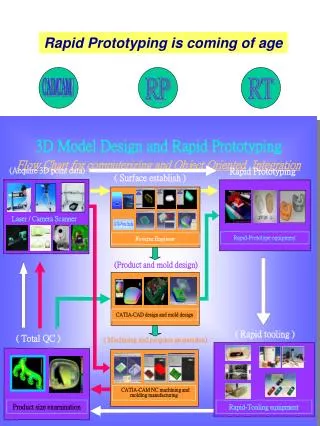
High Tech Product Design and Rapid Prototyping ME221 - MBA 290M - INFOSYS 290.8
High Tech Product Design and Rapid Prototyping ME221 - MBA 290M - INFOSYS 290.8 Prof. Paul Wright, A. Martin Berlin Chair in Mechanical Engineering Chief Scientist of CITRIS @ UC Berkeley Co-Director of the Berkeley Wireless Research Center

High Tech Product Design and Rapid Prototyping ME221 - MBA 290M - INFOSYS 290.8
E N D
Presentation Transcript
High Tech Product Design andRapid PrototypingME221 - MBA 290M - INFOSYS 290.8 Prof. Paul Wright, A. Martin Berlin Chair in Mechanical Engineering Chief Scientist of CITRIS @ UC Berkeley Co-Director of the Berkeley Wireless Research Center Co-Director of the Berkeley Manufacturing Institute Week 4
Will your company make motes/electronics/sensors? Very difficult, given the present state of other companies already in the field Will your company use motes for a product that assumes an infrastructure? Challenging to work with big governments, bureaucracies (e.g City of Berkeley, or BART)… Will you be a “smart-design” team like IDEO or Frog design that creates a product around a base-station and mobile system that can be used in a defined setting?... More likely to work… Product constraints
Use disposable or digital camera to capture user-needs & products, discuss in group Wednesday 9/20 – Group’s ‘first-idea’ on poster board “Glimpse Collage” 5% Collection of photographs at first sight but with a glimpse of what people need --- or what they might do with a proposed product This week’s homework (Wed.)
9/27 Sketch best concept + 200 word Scenario + 8-12 frame Story Board; these three items = 10% The Story Board is laid out to “tell a story” like a cartoon strip tells a story maybe without any words Our Story Board is not a cartoon in the “funny” sense (though it can be if you want to) … More that it can temporally tell how the user interacts with the product … Looking ahead one assignment
The Moisture Peak is a moisture tool that is a wireless moisture meter for detecting water on or beneath various surfaces. This device will include a hand held device called the “Peak” and a detachable pin set called the “Probe”. Product Scenario Peak Pencil Sketch Probe
4 weeks later Boy, I’m glad you bought the Moisture Peak, look how good our tomatoes turned out this season!!
Energy products (Nate Ota) Healthcare products (Ravi Nemana and Trevor Pering) But of course you have a free choice of any other topic that is creative First some possible examples from Ravi Mote review A new paradigm for distributed sensing Products for this semester
Small, low-cost, low-power computer (mote) The computer monitors one or more sensors: temperature, light, sound, position, acceleration, vibration, stress, weight, pressure, humidity, etc. The computer(s) connect to the base-station and/or other motes with a radio link. The radio link we will use allows a mote to transmit at a 50m range indoors / 125m range outdoors Power consumption, size and cost are the barriers to longer distances. Since a fundamental concept with motes is tiny size (and associated tiny cost), small and low-power radios are normal, not seen to be a disadvantage. Main “take away today” Since mid-90s = convergence of sensing, computing and communication
“Pico Cube” Macro to Micro Computers Stand alonecomputers 1960s Connected computers 1980s Distributed computers 2000s “Smart Dust” 2010 Vast reduction in cost, but additional capability Adapted from Various Sources: E.g. G. Bell, R. Newton, J, Rabaey, D. Culler, DR research team
Sensor (AtoD) linked to a ‘tiny’ computer Possible to do some local averaging etc Digital information shared with other computers in a network using “garbage band” frequencies 450 MHz 900 MHz 2.4 GHz Point to point Star Mesh Basic: Sensing + Local Computing + Communications + Computing at a Base Station including a Decision (e.g. sensor shows an “out of desirable range”)
E-M SPECTRUM ELECTRO MAGNETIC SPECTRUM LF HF UHF MICROWAVE LIGHT XRAYS AM RADAR FM. TV CELL Cosmic Gamma XRays 13.56 MHz InfraRed Rainbow UltraViolet 900 MHz 2.45 GHz 134 KHz 125 KHz
Please go to this website to see the hardware and software we will be using Tmote Sky hardware platform The Tmote Sky sensor suite is an on-board sensor suite that can be optionally included with each Tmote Sky device. The sensor suite includes humidity, temperature, photosynthetically active (PAR), and total solar radiation (TSR) sensors. The humidity and temperature sensor is produced by Sensirion, and the light sensors are produced by Hamamatsu. Boomerang 2.0.4 software for sending information between motes (e.g. a temperature signal) Motes: http://www.moteiv.com/
How Things Connect motes e.g. your application Port Serial Forwarder e.g. REM USB conn. Trawler Base station Programming Board Internet Trawler is a client of the serial forwarded server (makes sensor network data available to higher level applications) you
250kbps 2.4GHz IEEE 802.15.4 Chipcon Wireless Transceiver Interoperability with other IEEE 802.15.4 devices 8MHz Texas Instruments MSP430 microcontroller (10kB RAM, 48kB Flash) Integrated ADC, DAC, Supply Voltage Supervisor, and DMA Controller Integrated onboard antenna with 50m range indoors / 125m range outdoors Optional Integrated Humidity, Temperature, and Light sensors IEEE 802.15.4 compliant device
Wireless mesh networking 250kbps radio 10kB RAM 48kB flash 1MB storage Integrated on-board antenna providing up to 125 meter range 12-bit ADC and DAC USB protocol for programming Summary version: IEEE 802.15.4 compliant device
Ultra low current consumption Fast wakeup from sleep (<6us) Hardware link-layer encryption and authentication Programming and data collection via USB 16-pin expansion support and optional SMA antenna connector TinyOS support : mesh networking and communication implementation FCC modular certification : conforms to all US and Canada regulations IEEE 802.15.4 compliant device
http://www.tinyos.net/faq.html TinyOS is an event-based operating system intended for use in sensor networks. TinyOS uses a programming model that is based on the concept of ‘integrating' software components together to produce a working program. TinyOS is developed for ad-hoc communication, not reliability Limited resources (memory) requiring very efficient resource allocation ..http://www.tinyos.net/faq.html<<
Real Performance of TinyOS Packet Loss Better Worse Increasing Transmission Frequency Shane Erickson, SUPERB
Non-blocking Asynchronous Events (I hear something on the radio) Commands (turn on the light) Tasks (average the last 10 sensor values) Sum of components together = Application TinyOS: Not a traditional OS = non-blocking event-based app-specific scheduler
sensing application application Routing Layer routing Messaging Layer messaging UART Packet Radio Packet packet Radio byte UART byte Temp byte photo SW HW RFM i2c ADC bit clocks Visualization of TinyOS Source: Culler et al.
Backup slides Anticipating FAQs on motes versus RFIDs Looking ahead to a future week
A. Low Frequency LF (125 KiloHertz) and High Frequency HF (13.56 MegaHertz) The initial deployments of RFID operating at a low frequency band and relying on magnetic coil readers B. Ultra High Frequency UHF (900 MegaHertz) Now the current area of excitement for identifying many tags at once over a greater distance than LF or HF and relying on a radio frequency reader Comparison with RFID – 3 Main RFID types for purposes of “keeping things simple for now”
Every time we check out of a store like the Gap a simple one-bit RFID is used to check for a remaining security tag on your clothes Needs large cage like structure adjacent to door to emit strong enough magnetic field to a remaining tag One-bit (on/off) signal sounds alarm if a tag is present on item of clothing… And again to defuse any mystery about the technology…
Tag types • Passive Transponders (Tags) • LF, HF, UHF • Active Transponders (Tags) • UHF 400, 900 MHz, 2.45 GHz • Semi-Passive Tags such as the FasTrak • 900MHz or 2.45 GHz
Not an LF or HF passive tag Semi-active tag = FasTrak Battery inside (or some sort of power source) Radio Frequency allows wake up of system and battery provides the strength to send signal back to reader FasTrak on Bay Bridge
Passive – Gets energy from reader to power antennae Magnetic field loops around Tags work because reader produces a magnetic field zone --- field changes enough to activate chips – (door reader) Make larger antenna --- Or have a bigger flux to read further (Bigger net catches more fish) Low Frequency (125KHz) RFID
Same … Magnetic fields are always present again Pros Cons --- Pro = High Frequency allow photo-etching of antenna and so tags are very cheap to manufacture Trade offs = delicate so must be in limited package and the range of HF is often less than LF… (LF = more kinds of form factor) High Frequency HF (13MHz)
1. A magnetic coil (say on our lab door) is the physical interface between the reader and “the world” 2. An integrated circuit in the reader sends signals to an oscillator, creating an alternating current in the reader’s coil What happens inside the LF and HF readers?
3. The coil in the reader sits there creating a field for any tag that arrives and is close enough (a few inches say) to be activated… 4. So the magnetic coil in the reader interacts with the coil in the tag, to induce a current the causes a charge to flow into the capacitor on the tag…A diode in the tag’s circuit allows charge to build up When you walk up with your tag…
4. The charge accumulates in the capacitor and at a critical voltage level, the tags integrated circuit (IC) is activated and this transmits the ID 5. High and low levels of the digital signal from the IC – corresponding to the ones and zeros encoding the ID-number, turn the transistor on and off The circuit for the tag ID…
6. The transistor turns off and on, varying the resistance of the tag circuit, consequently creating a varying magnetic filed in the tags coil. The tag’s coil then interacts with the reader’s coil. 7. Magnetic fluctuations cause changes in the current flow from the reader’s coil to the reader’s A/D converter, and these are in the same pattern as the ones and zeros transmitted by the tag. Transmission…