Introduction to X-Ray Fluorescence Analysis
Introduction to X-Ray Fluorescence Analysis. Electromagnetic Radiation. 1Hz - 1kHz. 1kHz - 1014Hz. 1014Hz - 1015Hz. 1015Hz - 1021Hz. Extra-Low Frequency (ELF). Radio. Microwave. Infrared Visible Light. X-Rays, Gamma Rays. Ultraviolet. Low energy. High energy. Theory.


Introduction to X-Ray Fluorescence Analysis
E N D
Presentation Transcript
Introduction to X-Ray Fluorescence Analysis
Electromagnetic Radiation 1Hz - 1kHz 1kHz - 1014Hz 1014Hz - 1015Hz 1015Hz- 1021Hz Extra-Low Frequency (ELF) Radio Microwave Infrared Visible Light X-Rays, Gamma Rays Ultraviolet Low energy High energy
Theory • A source X-ray strikes an inner shell electron. If at high enough energy (above absorption edge of element), it is ejected it from the atom. • Higher energy electrons cascade to fill vacancy, giving off characteristic fluorescent X-rays. • Higher energy electrons cascade to fill vacancy, giving off characteristic fluorescent X-rays. • For elemental analysis of Na - U.
The Hardware • Sources • Optics • Filters & Targets • Detectors
Sources • End Window X-Ray Tubes • Side Window X-Ray Tubes • Radioisotopes • Other Sources • Scanning Electron Microscopes • Synchrotrons • Positron and other particle beams
End Window X-Ray Tube • X-ray Tubes • Voltage determines which elements can be excited. • More power = lower detection limits • Anode selection determines optimal source excitation (application specific).
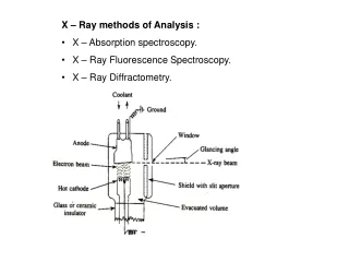
Side Window X-Ray Tube Be Window Glass Envelope HV Lead Target (Ti, Ag, Rh, etc.) Electron beam Copper Anode Filament Silicone Insulation
Isotope Fe-55 Cm-244 Cd-109 Am-241 Co-57 Energy (keV) 5.9 14.3, 18.3 22, 88 59.5 122 Elements (K-lines) Al – V Ti-Br Fe-Mo Ru-Er Ba - U Elements (L-lines) Br-I I- Pb Yb-Pu None none Radioisotopes • While isotopes have fallen out of favor they are still useful for many gauging applications.
Other Sources • Several other radiation sources are capable of exciting material to produce x-ray fluorescence suitable for material analysis. • Scanning Electron Microscopes (SEM) – Electron beams excite the sample and produce x-rays. Many SEM’s are equipped with an EDX detector for performing elemental analysis • Synchotrons - These bright light sources are suitable for research and very sophisticated XRF analysis. • Positrons and other Particle Beams – All high energy particles beams ionize materials such that they give off x-rays. PIXE is the most common particle beam technique after SEM.
Source Modifiers Several Devices are used to modify the shape or intensity of the source spectrum or the beam shape • Source Filters • Secondary Targets • Polarizing Targets • Collimators • Focusing Optics
Source Filters • Filters perform one of two functions • Background Reduction • Improved Fluorescence Source Filter Detector X-Ray Source
Filter Transmission Curve Titanium Filter transmission curve % T R A N S M I T T E D Absorption Edge Low energy x-rays are absorbed Very high energy x-rays are transmitted X-rays above the absorption edge energy are absorbed ENERGY Ti Cr The transmission curve shows the parts of the source spectrum are transmitted and those that are absorbed
Filter Fluorescence Method With Zn Source filter Target peak Continuum Radiation Fe Region ENERGY (keV) The filter fluorescence method decreases the background and improves the fluorescence yield without requiring huge amounts of extra power.
Filter Absorption Method Target peak With Ti Source filter Continuum Radiation Fe Region ENERGY (keV) The filter absorption Method decreases the background while maintaining similar excitation efficiency.
Secondary Targets • Improved Fluorescence and lower backgroundThe characteristic fluorescence of the custom line source is used to excite the sample, with the lowest possible backgroundintensity. • It requires almost 100x the flux of filter methods but gives superior results.
Secondary Targets Sample Detector X-Ray Tube Secondary Target • The x-ray tube excites the secondary target • The Secondary target fluoresces and excites the sample • The detector detects x-rays from the sample
Secondary Target Method With Zn Secondary Target Tube Target peak Continuum Radiation Fe Region ENERGY (keV) Secondary Targets produce a more monochromatic source peak with lower background than with filters
Secondary Target Vs Filter Comparison of optimized direct-filtered excitation with secondary target excitation for minor elements in Ni-200
Polarizing Target Theory • X-ray are partially polarized whenever they scatter off a surface • If the sample and polarizer are oriented perpendicular to each other and the x-ray tube is not perpendicular to the target, x-rays from the tube will not reach the detector. • There are three type of Polarization Targets: • Barkla Scattering Targets - They scatter all source energies to reduce background at the detector. • Secondary Targets - They fluoresce while scattering the source x-rays and perform similarly to other secondary targets. • Diffractive Targets - They are designed to scatter specific energies more efficiently in order to produce a stronger peak at that energy.
Collimators Collimators are usually circular or a slit and restrict the size or shape of the source beam for exciting small areas in either EDXRF or uXRF instruments. They may rely on internal Bragg reflection for improved efficiency. Sample Collimator sizes range from 12 microns to several mm Tube
Focusing Optics Because simple collimation blocks unwanted x-rays it is a highly inefficient method. Focusing optics like polycapillary devices and other Kumakhov lens devices were developed so that the beam could be redirected and focused on a small spot. Less than 75 um spot sizes are regularly achieved. Bragg reflection inside a Capillary Detector Source
Detectors • Si(Li) • PIN Diode • Silicon Drift Detectors • Proportional Counters • Scintillation Detectors
Detector Principles • A detector is composed of a non-conducting or semi-conducting material between two charged electrodes. • X-ray radiation ionizes the detector material causing it to become conductive, momentarily. • The newly freed electrons are accelerated toward the detector anode to produce an output pulse. • In ionized semiconductor produces electron-hole pairs, the number of pairs produced is proportional to the X-ray photon energy
Si(Li) Detector FET Window Super-Cooled Cryostat Dewar filled with LN2 Si(Li) crystal Pre-Amplifier Cooling: LN2 or Peltier Window: Beryllium or Polymer Counts Rates: 3,000 – 50,000 cps Resolution: 120-170 eV at Mn K-alpha
PIN Diode Detector Cooling: Thermoelectrically cooled (Peltier) Window: Beryllium Count Rates: 3,000 – 20,000 cps Resolution: 170-240 eV at Mn k-alpha
Silicon Drift Detector- SDD Packaging: Similar to PIN DetectorCooling: Peltier Count Rates; 10,000 – 300,000 cpsResolution: 140-180 eV at Mn K-alpha
Proportional Counter Window Anode Filament Fill Gases: Neon, Argon, Xenon, Krypton Pressure: 0.5- 2 ATM Windows: Be or Polymer Sealed or Gas Flow Versions Count Rates EDX: 10,000-40,000 cps WDX: 1,000,000+ Resolution: 500-1000+ eV
Scintillation Detector PMT (Photo-multiplier tube) Electronics Sodium Iodide Disk Window: Be or Al Count Rates: 10,000 to 1,000,000+ cps Resolution: >1000 eV Connector
Spectral Comparison - Au Si(Li) Detector 10 vs. 14 Karat Si PIN Diode Detector 10 vs. 14 Karat
Polymer Detector Windows • Optional thin polymer windows compared to a standard beryllium windows • Affords 10x improvement in the MDL for sodium (Na)
Detector Filters Filters are positioned between the sample and detector in some EDXRF and NDXRF systems to filter out unwanted x-ray peaks. Sample Detector Filter Detector X-Ray Source
Detector Filter Transmission Niobium Filter Transmission and Absorption % T R A N S M I T T E D EOI is transmitted Low energy x-rays are absorbed Very high energy x-rays are transmitted Absorption Edge X-rays above the absorption edge energy are absorbed ENERGY S Cl A niobium filter absorbs Cl and other higher energy source x-rays while letting S x-rays pass. A detector filter can significantly improve detection limits.
Filter Vs. No Filter Detector filters can dramatically improve the element of interest intensity, while decreasing the background, but requires 4-10 times more source flux. They are best used with large area detectors that normally do not require much power. Unfiltered Tube target, Cl, and Ar Interference Peak
Ross Vs. Hull Filters • The previous slide was an example of the Hull or simple filter method. • The Ross method illustrated here for Cl analysis uses intensities through two filters, one transmitting, one absorbing, and the difference is correlated to concentration. This is an NDXRF method since detector resolution is not important.
Wavelength Dispersive XRF Wavelength Dispersive XRF relies on a diffractive device such as crystal or multilayer to isolate a peak, since the diffracted wavelength is much more intense than other wavelengths that scatter of the device. Sample Detector Collimators X-Ray Source Diffraction Device
Diffraction The two most common diffraction devices used in WDX instruments are the crystal and multilayer. Both work according to the following formula. nl = 2d ´ sinq • n = integer • d = crystal lattice or • multilayer spacing • q = The incident angle • = wavelength Atoms
Multilayers While the crystal spacing is based on the natural atomic spacing at a given orientation the multilayer uses a series of thin film layers of dissimilar elements to do the same thing. Modern multilayers are more efficient than crystals and can be optimized for specific elements. Often used for low Z elements.
Soller Collimators Soller and similar types of collimators are used to prevent beam divergence. The are used in WDXRF to restrict the angles that are allowed to strike the diffraction device, thus improving the effective resolution. Sample Crystal
Cooling and Temperature Control • Many WDXRF Instruments use: • X-Ray Tube Coolers, and • Thermostatically controlled instrument coolers The diffraction technique is relatively inefficient and WDX detectors can operate at much higher count rates, so WDX Instruments are typically operated at much higher power than direct excitation EDXRF systems. Diffraction devices are also temperature sensitive.
Chamber Atmosphere Sample and hardware chambers of any XRF instrument may be filled with air, but because air absorbs low energy x-rays from elements particularly below Ca, Z=20, and Argon sometimes interferes with measurements purges are often used. The two most common purge methods are: Vacuum - For use with solids or pressed pellets Helium - For use with liquids or powdered materials
Changers and Spinners • Other commonly available sample handling features are sample changers or spinners. • Automatic sample changers are usually of the circular or XYZ stage variety and may have hold 6 to 100+ samples • Sample Spinners are used to average out surface features and particle size affects possibly over a larger total surface area.
Typical PIN Detector Instrument This configuration is most commonly used in higher end benchtop EDXRF Instruments.
Typical Si(Li) Detector Instrument This has been historically the most common laboratory grade EDXRF configuration.
Energy Dispersive Electronics Fluorescence generates a current in the detector. In a detector intended for energy dispersive XRF, the height of the pulse produced is proportional to the energy of the respective incoming X-ray. Signal to Electronics DETECTOR Element A Element B Element C Element D
Multi-Channel Analyser • Detector current pulses are translated into counts (counts per second, “CPS”). • Pulses are segregated into channels according to energy via the MCA (Multi-Channel Analyser). Intensity (# of CPS per Channel) Channels, Energy Signal from Detector
WDXRF Pulse Processing • The WDX method uses the diffraction device and collimators to obtain good resolution, so The detector does not need to be capable of energy discrimination. This simplifies the pulse processing. • It also means that spectral processing is simplified since intensity subtraction is fundamentally an exercise in background subtraction. • Note: Some energy discrimination is useful since it allows for rejection of low energy noise and pulses from unwanted higher energy x-rays.
Evaluating Spectra • K & L Spectral Peaks • Rayleigh Scatter Peaks • Compton Scatter Peaks • Escape Peaks • Sum Peaks • Bremstrahlung In addition to elemental peaks, other peaks appear in the spectra:
K & L Spectral Lines L beta • K - alpha lines:L shell e- transition to fill vacancy in K shell. Most frequent transition, hence most intense peak. L alpha K beta • K - beta lines:M shell e- transitions to fill vacancy in K shell. K alpha • L - alpha lines:M shell e- transition to fill vacancy in L shell. K Shell L Shell M Shell • L - beta lines:N shell e- transition to fill vacancy in L shell. N Shell
K & L Spectral Peaks K-Lines L-lines Rh X-ray Tube