Transformer Model
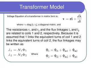
Transformer Model. Voltage Equation of a transformer in matrix form is:. where r = diag [r 1 r 2 ], a diagonal matrix, and.

Transformer Model
E N D
Presentation Transcript
Transformer Model Voltage Equation of a transformer in matrix form is: where r = diag [r1 r2], a diagonal matrix, and The resistances r1 and r2 and the flux linkages l1 and l2 are related to coils 1 and 2, respectively. Because it is assumed that 1 links the equivalent turns of coil 1 and 2 links the equivalent turns of coil 2, the flux linkages may be written as Where
Linear Magnetic System Reluctance is impossible to measure accurately, could be determined using:
Flux Linkages The coefficients of the 1st two terms on the right–hand side depend upon the turns of coil 1 and the reluctance of the magnetic system; i.e. independent of coil 2. Similar situation exist in equation for 2
Self Inductances • From the previous equations one can define Self-Inductances: Where Ll1 and Ll2 are leakage inductances of coil 1 and 2 respectively. Lm1 and Lm2 are the magnetizing inductances of coils 1 and 2 respectively.
Magnetizing Inductances • The two magnetizing Inductances are related as: Where m the Magnetizing Reluctance being common for both coils. The mutual Inductances are defined:
Mutual Inductances Mutual Reluctance being common for both Circuits; Mutual Inductances are related to Magnetizing Inductances too:
Flux Linkages • Flux Linkages may be written as: = Li Where
Flux Linkages • The Flux Linkage may also be derived based on self and mutual inductances:
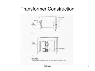
Example 1A It is instructive to illustrate the method of deriving an equivalent T circuit from open- and short-circuit measurements. For this purpose let us assume that when coil 2 of the two-winding transformer shown in Fig. is open-circuited, the power input to coil 1 is 12 W with an applied voltage is 100 V (rms) at 60 Hz and the current is 1 A (rms). When coil 2 is short-circuited, the current flowing in coil 1 is 1 A when the applied voltage is 30 V at 60 Hz. The power during this test is 22 W. If we assume Ll1= L’l2, an approximate equivalent T circuit can be determined from these measurements with coil 1 selected as the reference coil.
Equivalent T Circuit of Transformer Where i’2 =(N2/N1)i2
Example 1….. The Power may be expressed: Where are phasor and is the phase angle between them. Solving for during the open circuit test, we have:
Example 1…… as a reference phasor and in an inductive circuit of the transformer I phasor would lag behind by the angle of =83.70 V I Z, the impedance may therefore be determined by: That suggests that Xl1+Xm1 = 109.3, while r1 =12
Example 1……. For short circuit test i1= -I’2 because transformers are designed so that Xm1>> |r’2+jX’12|. Hence using phase angle equation: In this case input Impedance is (r1+r’2)+j(Xl1+X’l2) and that is determined by: That means r’2 = 10 and Xl1=X’l2 both are 10.2
Example 1…. That leads to conclusion that: Xm1= 109.3 -10.2 =99.1 Hence other parameters are: r1 = 12 Lm1 = 262.9mH r’2 = 10 Ll1 = 27.1mH L’l2 = 27.1mH V1 E1 I1 V’2
Flux Linkage of a Coil Fig. 1 shows a coil of N turns. All these N turns link flux lines of Weber resulting in the N flux linkages. In such a case: • Where • N is number of turns in a coil; • e is emf induced, and • is flux linking to each coil
Design of Transformer • Let's try to proportion a transformer for 120 V,60 Hz supply, with a full-load current of 10 A. The core material is to be silicon-steel laminations with a maximum operating flux density Bmax = 12,000 gauss. This is comfortably less than the saturation flux density, Bsat. The first requirement is to ensure that we have sufficient ampere-turns to magnetize the core to this level with a permissible magnetizing current I0A.
Design of Transformer…. • Let's choose the magnetizing current to be 1% of the full-load current, or 0.1 A. The exact value is not sacred; this might be thought of as an upper limit. Here, we will assume a simple, uniform magnetic circuit for simplicity. If l is the length of the magnetic circuit, H is 0.4πN(√2I0)/l, and the magnetization curve for the core iron gives the H required for the chosen Bmax. From this, we can find the number of turns, N, required for the primary.
Design of Transformer • We could also estimate the ampere-turns required by using an assumed permeability μ. Experience will furnish a satisfactory value. It is not taken from the magnetization curve, but from the hysteresis loop. Let's take μ = 1000. Then, N = Bmaxl / 0.4π√2 μI0. If we estimate l = 20 cm, the number of primary turns required is N = 1350. The rms voltage induced per turn is determined from Faraday's Law: √2 e = (2πf)BmaxA x 10-8. Now, e must be 120 / 1350 = 0.126 V/turn, f is 60, and Bmax = 12,000 gauss. We know everything but A, the cross-sectional area of the core. We find A = 2.8 cm2.
Design of Transformer • Powdered iron and ferrite cores have low Bsat and permeability values. A type 43 ferrite has Bsat = 2750 gauss, but a maximum permeability of 3000, and is recommended for frequencies from 10 kHz to 1 MHz. Silicon iron is much better magnetically, but cannot be used at these frequencies. The approximate dimensions of an FT-114 ferrite core (of any desired material) are OD 28 mm, ID 19 mm, thickness 7.5 mm. The magnetic dimensions are l = 74.17 mm, A = 37.49 mm2, and volume 2778 mm3. Similar information is available for a wide range of cores. There are tables showing how much wire can be wound on them, and even the inductance as a function of the number of turns.
Design Parameters B = /A Laminated Core A: X-section Area l average length N number of turns
Flux Density & MMF Bmax