Memory organization
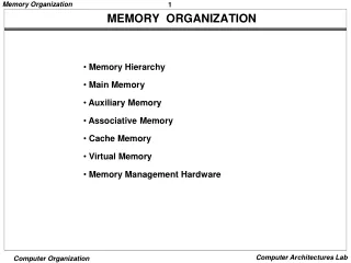
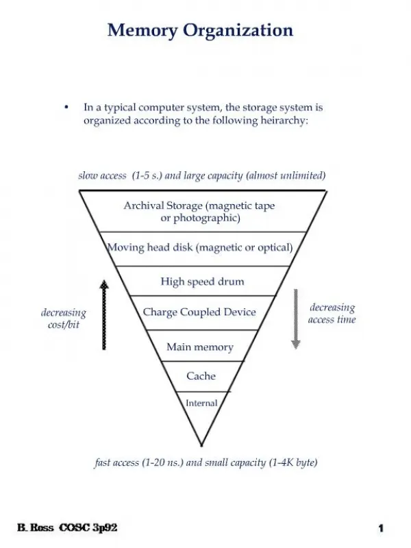
Memory organization. Three categories: Internal processor memory Main memory Secondary memory Cache memory The choice of a memory device to built a memory system depends on its properties. Goal of memory organization. To provide high averg performance with low averg cost per bit:

Memory organization
E N D
Presentation Transcript
Three categories: • Internal processor memory • Main memory • Secondary memory • Cache memory • The choice of a memory device to built a memory system depends on its properties.
Goal of memory organization • To provide high averg performance with low averg cost per bit: • Hierarchy of different memory devices • Automatic storage allocation method • Virtual memory concepts • Efficient memory interface to provide higher data transfer rate.
Memory-device characteristics • Cost, c = C/S dollars/bit • Access time, tA • Time spent to transfer a data to the output after receiving a read- request. • Access modes • Random-access memory (RAM). • Serial access • Semirandom or direct access • Alterability • Read-only, ROM • PROM, EPROM • Read-write, RAM
Permanence of storage • Destructive read-out • Non-destructive read-out • Dynamic storage, refreshing • Volatility.
Cycle time and data-transfer rate • Bandwidth, bM =w/tM • tA may not be equal to tM,cycle time. • Physical characteristics • Physical size • Storage density • Energy consumption • Reliability: mean time to failure (MTTF)
Semiconductor RAMs Va • Static RAM • Data remains as long as power is supplied • Read: add line active, data line connected to sense amp • Write: Add line active, data line connected to data (low or high), Vb is connected to V1/2 • Dynamic RAM • Data goes away within a millisecond even power is there. • Refreshing is required R R V1/2=Vb Data line Add line Bipolar static RAM cell add data GND Dynamic MOS cell
RAM organization Va Vb • Access circuitry has a very significant effect on total cost of any memory unit. To reduce the cost the organization has two essential features: • The storage cells are physically arranged in rectangular arrays of cells. This is to facilitate layout of the connections between the cells and the access circuitry. • The memory address is partitioned into d components so that address Aiof cell Ci becomes a d-dimensional vector (Ai,1,Ai,2, . . . , Ai,d) = Ai. Each of the d parts of an address word goes to a different address decoder and a different set of address drivers. A particular cell is selected by simultaneously activating all d of its address lines. Decoder A0 A1 Z1 Z0 X1 CE WE X0 Structure of 4x2-bit RAM. 1-dimensional memory
RAM Design • 2mxn bit RAM IC. • m represent no of address lines. • n represent word size. 2mxn RAM m n Address A Data D OE CS WE A RAM IC
RAM design contd. • Increasing word size. • Increasing number of words. • Given that Nxw bit RAM ICs, design N’xw’ bit RAM, where N’>N and/or w’>w: • Construct a pxq array of given RAM ICs, where p=ceil{N’/N}, q=ceil{w’/w} • Each row stores N words • Each column stores a fixed set of w bits from every words
Increasing number of words 2mxw RAM w 2-bit are added at the msb position of m+2 bit address WE CS OE 2mxw RAM 1 to 4 decoder WE CS OE 2mxw RAM E 2 CS OE WE 2mxw RAM m+2 m w Address A Chip select CS CS OE WE WE OE
Structure of commercial 8Mx8 bit DRAM chip • 23 address lines are multuplexed into 13 external address lines. • Page mode • Refresh cycle time is 64ms. • If one-row read operation takes 90ns, then time needed to refresh the DRAM is 90nsx8192 = 0.737ms
Other semiconductor memories • ROMs • ROM • PROM • EPROM: program randomly erase in bulk off-line • EEPROM • Flash memory • Reading is random but writing is in blocks
Fast RAM interface • . If we need to supply a faster external processor with individually accessible n-bit words, then two basic ways to increase data-transfer rate across its external interface by a factor of S • Use a bigger memory words: design the RAM with an internal memory word size of w=Sn bits. Sn bits is used as one unit to be accessed in one memory cycle time TM. • Access more than one words at a time: partition the RAM into S separate banks M0, M1, …, MS-1, each covering part of the memory address space and each provided with its own addressing ckt. Need fast ckt inside the RAM to assemble and disassemble the words being accessed.
Both require fast p-to-s and s-to-p ckts at the memory processor interface. • Normally S words produced or consumed by the processor have consecutive address. Their placement in the physical memory uses Interleaving technique.
Address Interleaving • Let Xh, Xh+1, … be words that expected to be accessed in sequence. They normally be placed in consecutive memory locations Ai,Ai+1, …in the RAM. • Assign Aito bank Mj if j=i (modulo S). • If S = 2p, then least significant p bits of a memory add immediately identify the memory bank where it belongs to.
Magnetic surface recording • Surface of magnetic medium: ferric oxide • If each track has a fixed capacity N words, and rotate at r revolutions/s. Let n be the number of words/block, its data can be transferred in n/(rN) s. The aver latency is 1/(2r) s. If ts is avrg seek time, then time needs to access a block of data, tB = ts + 1/(2r) + n/(rN) • Magnetic disk drive • Platters • heads • Tracks: • Sectors: sector header, inter-sector gap • Cylinders
Magnetic tape • Data is stored in longitudinal tracks. Older tapes had 9 parallel tracks. Now about 80 tracks are used. • A single head can read/write all tracks simultaneously. • Along the tracks data are stored in blokcs. Large gaps are inserted between adjucent blocks so that tape can be started and stopped between blocks.
Optical memories • CD-ROMs • Bits are stored in 0.1 µm wide pits and lands. • Access time is about 100ms, data transfer rate is 3.6 MB/s (for 24x; x = 150KB/s)
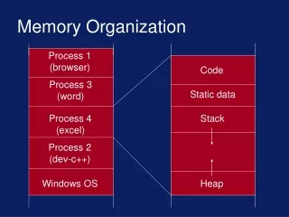
Memory hierarchy M2 M1 Main memory D • Normally holds • ci > ci+1 • tAi < tAi+1 • si < si+1 • Cache • Write-through • Write-back Secondary CPU I Main memory D I Secondary CPU D I M1 M2 M3 Cache Main memory D L2 CPU L1 Secondary I M1 M2 M3 Cache
Virtual memory • Memory hierarchy comprising of different memory devices appears to the user program as a single, large, directly addressable memory. • Automatic memory allocation, and efficient sharing • Makes program independent of main memory space • Achieve relatively low cost/bit and low access time. • A memory location is addressed by virtual address V, and it is necessary to map this address to the actual physical address R, f:VR
Locality of references • Over short term, the addresses generated by a program tend to be localized and are therefore predictable. • Page mode: info is transferred between Mi and Mi+1 as a block of consecutive words. Spatial locality. • Temporal locality: loop instru has high frequency of references.
Let instruction I is stored at address A and assigned to Mi ≠M1. • Next instru is most likely be at A+1. • Information are paged, Spi, Spi-1, Spi-2 etc. • Transfer Spi , containing I to MI from Mi+1. • Transfer Spi-1 containing I to Mi-1 from Mi. • Transfer Spi-2 containing I to Mi-2 from Mi-1. • And so on… • Transfer Sp1 containing I to M1 from M2.
Design objectives • To achieve performance close to that of the fastest device M1 and a cost per bit close to that of the cheapest device Mn. • Performance depends on the factors: • Address reference statistics • Access time of each level Mi relative to CPU. • Storage capacity of each level • Page size of successive levels • Algorithm used to determine the page to be transferred.
Cost and performance • Consider a 2 level memory hierarchy (M1,M2). Avrg cost per bit of the system is • Hit ratio, H • Probability that a logical address generated by the CPU referers to information stored in M1. • H = 1 is desirable but difficult to achieve • A set of representative program is executed or simulated. If N1 and N2 are the address references satisfied by M1 and M2 respectively, then hit ratio, • H is highly program dependent, 1-H is called miss ratio
Access efficeincy • Let tA1and tA2 be the access times of M1and M2, respective, relative to the CPU. The avrg access time is • Block transfer time tB. tA2 = tB+ tA1. Equ.(1) yields • Usually tB >> tA1. Therefore, tA2≈ tB. • Let access-time ratio, r = tA2/tA1 of the two level memory. • Access efficiency e = tA1/ tA. e=1 is desirable.
Three Q for VM • When should the swapping take place? • Demand swapping • Anticipatory swapping • Requires relative long range prediction, difficult • Where should the block being transferred into main memory be placed? • allocation policy • Preemptive • Non preemptive • Thrashing • How many words are transferred during each swap, i.e. the page size?
Address mapping • Address mapping and translation is carried out at different stage in life of a prog • By the programmer while writing the prog • By the compiler during compilation • By the loader at initial prog-load time • By run-time memory management HW and/or software • Static allocation, dynamic allocation
Static allocation • Effective add, Base add, Displacement • Aeff= B+D or Aeff = B.D • Limit address, Li • Bi<=Ap<= Li • D Aeff • 0 B • B+1 • . • i B+I • m-1 B+m-1 B W0 W1 … Wi … Wm-1 B1 B1 Blk K1 L1 Blk K1 L1 B’2 Blk K2 L2 B2 Blk K2 B3 L3 L2 Blk K3
Virtual page number offset page frame offset Dynamic address-trans system • Memory address table. • Main memory • CPU registers: base or relocation registers. • Paged, 2k to 16 k • Page table base add • Page table • Page frame • Control bits • Validity • Update • restrictions Virtual add from processor Page table base add Page table add Page table Page frame in memory Ctlr bits Physical add in memory
Dynamic address-trans system • Page table should be in MMU. • Page Table can be long. • TLB (translation lookaside buffer) is referred to as an address cache. • Set-associative memory TLB Translation table containing part of the page table AV BV D AR BR D To memory system
Main Memory Allocation • Placement of info blocks from secondary memory to main memory is called main memory allocation. • Memory map contains • Occupied memory list • Each entry has a block name, base add of the region, block size and some control info • Available space list • Add of free memory blocks, and sizes. • Directory for secondary. • List which contains the directories for all the blocks associated to currently executing programs
Non-preemptive allocation • Does not overwrite or move existing blocks to make room for incoming blocks. • Algorithm for paged segment. • Easy to implement since all blocks are of same size; just finds an empty page frame and then allocate it to the incoming block. • Algorithms for unpaged segment • First fit: • if block Ki has ni words, find a space of size ≥ni from the available space list. • Best fit • Searches the whole list of available space for regions, nj ≥ ni, and allocate a block such that nj – ni is minimized.
gap1 Example: Non-preemptive Available space list: Incoming blocks: K4=100 words K4 K5=250 words K5 Allocation of K4 and K5 0 0 0 Block K1 Block K1 K1 300 300 400 550 650 Block K2 Block K2 Block K2 800 800 900 gap2 Block K3 Block K3 Block K3 Initial state Best Fit First Fit
Preemptive allocation • Non-preemptive policy is not efficient in all situations; overflow may occur even when the memory is partially full. Relocation of occupied space can improve the efficiency. • Relocation is done in 2 ways: • Relocate a block to a different position within M1 • Deallocate a block from M1 memory using a replacement policy • Dirty blocks, clean blocks • Relocation by compaction • Replacement policies – to achieve max. Hit ratio.
Optimal replacement policy – find the block for replacement that has minimum chance to be referenced next time. • First a simulation run generates Block Address trace, S. Then find a max(tj – ti) for all locations. Construct optimal sequence SOPT. • Can be extremely time consuming • Two most common replacement policies: • FIFO (first-in first-out) • Simple. But frequently used block (like a loop) may be replaced because it is oldest block. • LRU (Least recently used) • Selects the block least recently accessed by the processor. • Avoids the replacement of freq used blocks. • Slightly difficult to implement
Performance of RP • Block hit ratio, • If n*be the avrg number of consecutive word address references within a block, then H can be found from H* using following relation:
Comparisons of RPs • Main memory has capacity of 3 pages. Program Q requires to reference 5 distinct pages, Pi, where i = 1,2,3,4,5, and i is the page address. Page address stream is 2 3 2 1 5 2 4 5 3 2 5 2 which means the first page referenced is P2, the second page is P3 etc. • Next block to be selected is marked *. • LRU recognized that P2 and P5 are referenced more frequently than other pages. • Highest hit ratio is achieved by OPT, lowest is FIFO. LRU is close to OPT.
Stack replacement policies • Cost and performance of a memory hierarchy can be measured by c and tA. • Once these parameters are chosen the hit ratio must be computed for various system configurations. H depends on • Types of address streams • Averg block size • Capacity of main memory • Replacement policy
Let A be any page address stream of length L to be processed using a replacement policy R. let t denote the point in time when first t pages of A have been processed. Let n be variable denoting the page capacity of M1. Bt(n) denotes the set of pages in M1 at time t, and Lt denotes the number of distinct pages that have been encountered at time t. R is called stack algorithm if it has the following inclusion property: • LRU retains n most recently used pages. It is stack algorithm. But FIFO is not.
Segments and page • Page - Basic unit of memory info for swapping purpose in a multilevel memory system. • Page-frame • Segments – higher level info blocks corresponding to logical entities e.g program or data sets. A segments can be translated into one or more pages. • Segment add, displacement. when a segment is not currently resident in the M1 memory, it is entirely transferred from the secondary memory M2. • Segment table. • Main adva: • Segments are independent, can b recompiled at any time without affecting others. • Efficient memory use, program area protection. • Variable length segment can easily be allocated in the main memory by the help of paging.
Burroughs B6500 segmentation • Each program has a segment called its program reference table PRT, which serves as it segment table. • Segment descriptor • Intel 80x86 and pentium series have four 16 bit segment registers forming a segment table
Advantages of segmentation • Segment boundaries corresponds to natural program and data boundaries. Because of their logical independence, a program segment can be changed or recompiled at any time without affecting other segments. • Implementation of access rights and scopes of program variables have been easy. • Implementation of Stack and queues have been easy as the segment can be of variable length.
pages • Fixed length block • page table • Page add, displacement • Page fault. • External fragmentation • Internal fragmentation • Segments can be assigned over a non-contiguous area in the memory by the use of paging.
Effect of page size, SP • Storage utilization, effective data-transfer rate. • If SS >> SP, the last page assigned to a segment should contain Sp/2 words. • No. of page table is approx. SS/SP words. Memory-space overhead with each segment • Space utilization,
Optimum page size is obtained when S is minimized. • Optimum space utilization, • The effect of page size on hit ratio is complex • When Sp is small, H increases with Sp . • When Sp exceeds a certain value, H begins to decreases.


![[Packet] My Memory Organization](https://cdn1.slideserve.com/1905829/packet-my-memory-organization-dt.jpg)