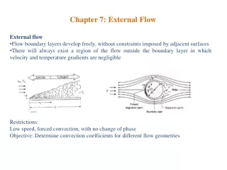
Chapter 7 COMPRESSIBLE FLOW
Chapter 7 COMPRESSIBLE FLOW. In this chapter on compressible flow, one new variable enters, the density, and one extra equation is available, the equation of state, which relates pressure and density.


Chapter 7 COMPRESSIBLE FLOW
E N D
Presentation Transcript
In this chapter on compressible flow, one new variable enters, the density, and one extra equation is available, the equation of state, which relates pressure and density. • The other equations-continuity, momentum, and the first and second laws of thermodynamics - are also needed in the analysis of compressible fluid-flow situations. When density changes are gradual and do not change by more than a few percent, the flow may be treated as incompressible with the use of an average density. • The following topics are treated in this chapter: prefect-gas relations, speed of a sound wave, Mach number, isentropic flow, shock waves, Fanno and Rayleigh lines, adiabatic flow, flow with heat transfer, isothermal flow, and the analogy between shock waves and open-channel waves.
7.1 PERFECT-GAS RELATIONS • Perfect gas is defined as a fluid that has constant specific heats and follows the law (7.1.1) • in which p and T are the absolute pressure and absolute temperature, respectively, ρ is the density, and R the gas constant. • In general, the specific heat cv is defined by (7.1.2) • The specific heat cp at constant pressure is defined by (7.1.3)
For perfect gases Eq. (7.1.2) becomes (7.1.4) • and Eq. (7.1.3) becomes (7.1.5) • Then, from • differentiating gives • and substitution of Eqs. (7.1.4) and (7.1.5) leads to (7.1.6)
The specific heat ratiok is defined as the ratio (7.1.7) • Solving with Eq. (7.1.6) gives (7.1.8)
Entropy Relations • The first law of thermodynamics for a system states that the heat added to a system is equal to the work done by the system plus its increase in internal energy [Eq. (3.8.4)]. In terms of the entropy s the equation takes the form (3.8.6) • The internal-energy change for a perfect gas is (7.1.9) • and the enthalpy change is (7.1.10) • The change in entropy (7.1.11)
may be obtained from Eqs. (7.1.4) and (7.1.1). Alter integrating, (7.1.12) • By use of Eqs. (7.1.8) and (7.1.1), Eq. (7.1.12) becomes (7.1.13) • or (7.1.14) • And (7.1.15) • These equations are forms of the second law of thermodynamics.
From Eq. (7.1.14) for s2=s1, (7.1.16) • Equation (7.1.16) combined with the general gas law yields (7.1.17) • The enthalpy change for an isentropic process is (7.1.18) • The polytropic process is defined by (7.1.19) • and is an approximation to certain actual processes in which p would plot substantially as a straight line against ρ on log-log paper.
Example 7.1 • Helium has R=2.077 kJ/kg K. Find cv and k and check against Table C.3. Solution
Example 7.2 • Compute the value of R from the values of k and cp for air and check in Table C.3. Solution • From Eq. (7.1.8)
Example 7.3 • Determine the entropy change in 4.0 kg of water vapor when the initial conditions are p1=42 kPa, t1=430C and the final conditions are p2=280 kPa, t2=30C. Solution • From Eq.(7.1.15) and Table C.3
7.2 SPEED OF A SOUND WAVE; MACH NUMBER • The speed of a small disturbance in a conduit can be determined by application of the momentum equation and the continuity equation. • The question is first raised whether a stationary small change in velocity, pressure, and density can occur in a channel. By referring to Fig. 7.1 the continuity equation can be written • in which A is the cross-sectional area of channel. The equation can be reduced to • When the momentum equation (3.11.2) is applied to the control volume within the dotted lines,
Figure 7.1 Steady flow in prismatic channel with sudden small change in velocity, pressure, and density.
If ρdV is eliminated between the two equations, (7.2.1) • The equation for speed of sound (7.2.2) • may be expressed in several useful forms. The bulk modulus of elasticity can be introduced: • in which V is the volume of fluid subjected to the pressure change dp. Since
K may be expressed as • Then, from Eq.(7.2.2), (7.2.3) • This equation applies to liquids as well as gases. • Since the pressure and temperature changes due to passage of a sound wave and extremely small, the process is almost reversible. • In the limit, the process may be considered to be isentropic, (7.2.4)
or, from the perfect-gas law p=ρRT, (7.2.5) • which shows that the speed of sound in a perfect gas is a function of absolute temperature only. • The Mach number has been defined as the ratio of velocity of a fluid to the local velocity of sound in the medium, (7.2.6) • The Mach number is a measure of the importance of compressibility. In an incompressible fluid K is infinite and M=0. For perfect gasses. (7.2.7) • when the compression is isentropic.
Example 7.6 • Carbon tetrachloride has a bulk modulus of 1.124 GPa and a density of 1593 kg/m3. What is the speed of sound in the medium? Solution
Example 7.7 • What is the speed of sound in dry air sea level when t=200C and in the stratosphere when t=-200C ? Solution • At sea level, from Eq.(7.2.5) • and in the stratosphere
7.3. ISENTROPIC FLOW • Frictionless adiabatic, or isentropic, flow is an ideal that cannot be reached in the flow of real gases. • Some very general results can be obtained by use of Euler's equation (3.5.8), neglecting elevation changes, (7.3.1) • and the continuity equation (7.3.2)
Differentiating ρAV and then dividing through by ρAV gives (7.3.3) • From Eq.(7.2.2) dρ is odtained and sudstituted into Eq.(7.3.1) yielding (7.3.4) • Eliminating dρ/ρ in the last two equations and rearranging give (7.3.5) • The assumptions underlying this equation are that the flow is steady and frictionless. No restrictions as to heat transfer have been imposed. • Equation (7.3.5) show that, for subsonic flow (M<1), dA/dV is always negative; i.e., the channel area must decrease for increasing velocity.
When the analysis is restricted to isentropic flow, Eq. (7.1.16) may be written (7.3.6) • Differentiating and substituting for dp in Eq.(7.3.1) give • Integration yields or (7.3.7)
From p=ρRT (7.3.8) • For adiabatic flow from a reservoir where conditions are given by p0, ρ0, T0 at any other section (7.3.9) • In terms of the local number V/c, with c2=kRT (7.3.10)
From Eqs. (7.3.10) and (7.1.17), which now restrict the following equations to isentropic flow, (7.3.11) (7.3.12) • Flow conditions are termed critical at the throat section when the velocity there is sonic. Sonic conditions are marked with an asterisk. • By applying Eqs. (7.3.10) to (7.3.12) to the throat section for critical conditions (for k=1.4 in the numerical portion), (7.3.13) (7.3.14) (7.3.15)
The variation of area with the Mach number for the critical case is obtained by use of the continuity equation Eqs. (7.3.10) to (7.3.15). First (7.3.16) • in which A* is the minimum, or throat, area. Then (7.3.17) • Now, and , so that (7.3.18) • by use of Eqs.(7.3.13) and (7.3.10). In a similar manner (7.3.19)
By substituting the last two equations into Eq. (7.3.17) gives (7.3.20) • For gasses with k=1.40, Eq.(7.3.20) reduces to (7.3.21) • The maximum mass flow rate mmaxcan be expressed in terms of the throat area and reservoir conditions: • Replacing ρ0 by p0√(R0T0) gives (7.3.22)
For k=1.40 this reduces to (7.3.23) • The mass rate of flow m is obtained from (7.3.24) • This equation holds for any section and is applicable as long as the velocity at the throat is subsonic. It may be applied to the throat section, and for this section, from Eq. (7.3.14), • When the equals sign is used in the expression, Eq. (7.3.24) reduces to Eq. (7.3.22).
For maximum mass flow rate, the flow downstream from the throat may be either supersonic or subsonic, depending upon the downstream pressure. Substituting Eq. (7.3.22) for m in Eq. (7.3.24) and simplifying gives (7.3.25) • A may be taken as the outlet area and P as outlet pressure. For a given A*/A (less than unity) there will be two values of p/p0 between zero and unity, the upper value for subsonic flow through the diverging duct and the lower value for supersonic flow through the diverging duct. • For all other pressure ratios less than the upper value complete isentropic flow is impossible and shock waves form in or just downstream from the diverging duct. They are briefly discussed in the following section.
Example 7.9 • A preliminary design of a wind tunnel to produce Mach number 3.0 at the exit is desired. The mass flow rate is 1 kg/s for p0=90 kPa abs, t0=250C. Determine (a) the throat area, (b) the outlet area, and (c) the velocity, pressure, temperature, and density at the outlet. Solution • (a) The throat area con be determine form Eq. (7.3.23);
(b) The area of outlet is determined from Table C.4: • (c) From Table C.4 • From the gas law
hence, at the exit • From the continuity equation
Example 7.10 • A converging-diverging air duct has a throat cross section of 372 cm2 and an exit cross section of 929 cm2. Reservoir pressure is 210 kPa abs, and temperature is 16 0C. Determine the range of Mach numbers and the pressure range at the exit for isentropic flow. Find the maximum flow rate. Solution • From Table C.4 [Eq.(7.3.21)] M=2.44 and 0.24. Each of these values of Mach numbers at the exit is for critical conditions; hence, the Mach number range for isentropic flow is 0 to 0.24 and them one value 2.44.
From Table C.4 [Eq.(7.3.11)] M=2.44, p=210×0.064=13.44 kPa, and M=0.24, p=210×0.961=201.8 kPa. The downstream pressure range is then from 201.8 to 210 kPa abs, and the isolated point is 13.44 kPa. • The maximum mass flow rate is determined form Eq.(7.3.23):
Example 7.11 • A converging-diverging duct in an air line downstream from a reservoir has a 50-mm-diameter throat. Determine the mass rate of flow when p0=0.8 MPa abs, t0=330C, and p=0.5 MPa abs at the throat. Solution • From Eq.(7.3.24)
7.4 SHOCKWAVES • In one-dimensional flow the only type of shock wave that can occur is a normal compression shock wave, as illustrated in Fig. 7.3. • In this section the normal shock wave in a diffuser is studied, with isentropic flow throughout the tube, except for the shock wave surface. The shock wave occurs in supersonic flow and reduces the flow to subsonic flow, as proved in the following section. • It has very little thickness, of the order of the molecular mean free path of the gas. The controlling equations for adiabatic flow are (Fig.7.3) • Continuity: (7.4.1) • Energy: (7.4.2)
The momentum equation (3.11.2) for a control volume between sections 1 and 2 becomes (7.4.3) • The value of p2 is (7.4.4) • By combination of the continuity and momentum equations (7.4.5) • The Rankine-Hugoniot equations are obtained: (7.4.6) (7.4.7)
From Eq. (7.4.2), the energy equation, (7.4.8) • Dividing Eq.(7.4.3) by Eq. (7.4.3) gives • by use of Eq.(7.4.8), leads to (7.4.9) • which is satisfied by V1=V2 (no shock wave) or by (7.4.10) • It may be written (7.4.11)
An expression for change of entropy across a normal shock wave may be obtained in terms of M1 and k. From Eq.(7.4.4) (7.4.14) • From Eq. (7.4.12), (7.4.13) • Placing this value of p2/p1 in Eq. (7.4.7) yields • Substituting these pressure and density rations into Eq. (7.1.14) gives (7.4.14)
Example 7.12 • If a normal shock wave occurs in the flow of helium, p1=7 kPa, t1=5°C, V1= 1372 m/s, find p2, ρ2, V2 and t2. Solution • From Table C.3, R = 2077, k = 1.66. and • From Eq. (7.4.4) • From Eq. (7.4.5)
From Eq. (7.4.1) • and
7.5 FANNO AND RAYLEIGH LINES • To examine more closely the nature of the flow change in the short distance across a shock wave, where the area may be considered constant, the continuity and energy equations are combined for steady, frictional, adiabatic flow. • The lines on such a plot for constant mass flow G are called Fanno lines (Fig. 7.3). The most revealing plot is that of enthalpy against entropy, i.e., an hs diagram. • The entropy equation for a perfect gas, Eq. (7.1.14), is (7.5.1) • The energy equation for adiabatic flow with no change in elevation, from Eq. (7.4.2), is (7.5.2)
And the continuity equation for no change in area, from Eq. (7.4.1), is (7.5.3) • The equation of state, linking h, p, and ρ, is (7.5.4) • By elimination p, ρ, and V from the four equations (see Fig. 7.4), (7.5.5) • By indicating by subscript a values at the maximum entropy point,
After substituting this into Eq. (7.5.2) to find Va, • and (7.5.6) • Hence, the maximum entropy at point a is for M = 1, or sonic condition. For h> ha the flow is subsonic, and for h< ha the flow is supersonic. • The two conditions, before and after the shock, must lie on the proper Fanno line for the area at which the shock wave occurs. The momentum equation was not used to determine the Fanno line, and so the complete solution is not determined yet.
Rayleigh Line • Conditions before and after the shock must also satisfy the momentum and continuity equations. • Assuming constant upstream conditions and constant area, Eqs. (7.5.1), (7.5.3), (7.5.4), and (7.4.3) are used to determine the Rayleigh line. Eliminating V in the continuity and momentum equations gives (7.5.7) • Next, eliminating p from thus equation and the entropy equation gives (7.5.8) • Enthalpy may be expressed as a function of and upsteam condition, from Eq. (7.5.7): (7.5.9)
The value of maximum entropy is found by taking ds/dρ and dh/dρ from the equations; then by division and equating to zero, using subscript b for maximum point, • To satisfy this equation, the numerator must be zero and the denominator not zero. The numerator set equal to zero yields • For this value the denominator is not zero. Again, as with the Fanno line, sonic conditions occur at the point of maximum entropy. • Since the flow conditions must be on both curves, just before and just after the shock wave, it must suddenly change from one point of intersection to the other.
Converging-Diverging Nozzle Flow • Following the presentation of Liepmann and Roshko the various flow situations for converging-diverging nozzles are investigated. By use of Eq. (7.3.11) the area ratio is obtained as a function of pressure ratio (7.5.10) • Figure 7.5 is a plot of area ratio vs. pressure ratio and M, good only for isentropic flow (k = 1.4). • By use of the area ratios the distribution of pressure and Mach number along a given converging-diverging nozzle can now be plotted. Figure 7.6 illustrates the various flow conditions that may occur.
Figure 7.5 Isentropic relations for a converging-diverging nozzle (k=1.4).
Figure 7.6 Various pressure and Mach-number configurations for flow through a nozzle.
7.6 ADIABATIC FLOW WITH FRICTION IN CONDUITS • Gas flow through a pipe or constant-area duct is analyzed in this section subject to the following assumptions: • 1. Perfect gas (constant specific heats) • 2. Steady, one-dimensional flow • 3. Adiabatic flow (no heat transfer through walls) • 4. Constant friction factor over length of conduit • 5. Effective conduit diameter D equal to four times hydraulic radius (cross-sectioned area divided by perimeter) • 6. Elevation changes unimportant compared with friction effects • 7. No work added to, or extracted from, the flow.