Direct Methods of Level Measurement: Hook-Type Indicator and Sight Glass
Level measurement is crucial across industries, with various methods for liquids, gases, or solids stored in tanks. This guide covers direct measurement methods like Hook-Type Level Indicators and Sight Glasses, providing construction details, working principles, and advantages/disadvantages.

Direct Methods of Level Measurement: Hook-Type Indicator and Sight Glass
E N D
Presentation Transcript
CHAPTER 2LEVEL MEASUREMENT Direct Method Hydrostatic Pressure Type Electrical Type Microwave Level Switches Optical Level Detector Ultrasonic Level Detector Eddy Current Level Measurement Sensors Servicing of Level Measuring Instruments
VIDEO 1 VIDEO 2
Level Measurement Level is another common process variable that is measured in many industries. The method used will vary widely depending on the nature of the industry, the process, and the application. Level measurement – the act of establishing the height of a liquid surface in reference to a zero point.
What is measured? The measured medium can be liquid, gas or solid and stored in vessels (open/closed tanks), silos, bins and hoppers. Units of level can be expressed in: • feet (meters) • gallons (liters) • pounds (kilograms) • cubic volume (ft3, m3)
Selection Criteria When determining the type of level sensor that should be used for a given application, there are a series of questions that must be answered: • Open tank or closed tank? • Can the level sensor be inserted into the tank or should it be completely external? Contact or non-contact? • Continuous measurement or point measurement? • Direct or Indirect measurement? • What type of material is being measured? Liquid or Solid? Clean or Slurry?
Methods – Direct or Indirect (inferential) • Hydrostatic Head • Float • Load Cells • Magnetic Level Gauge • Capacitance Transmitters • Magnetostrictive • Ultrasonic • Microwave • Laser • Radar • Guided Wave Radar • Dip Stick • Vibration
Direct Methods • Direct methods sense the surface or interface of the liquid and is not affected by changes in material density (Specific Gravity) • Measures the process variable directly in terms of itself. Examples: • Hook-type Level Indicator • Sight Glass • Float- type • Dip Stick
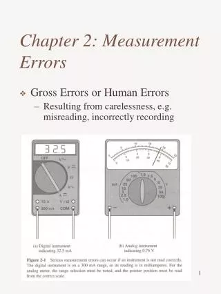
Hook-type Level Indicator • When the level of liquid in an open tank is measured directly on a scale, it is sometimes difficult to read the level accurately because of parallax error. Figure 2.1: Hook- type Level Indicator
Hook-type Level Indicator Construction • Consist of a wire of corrosion resisting alloy (such as stainless steel) about 0.063mm diameter, bent into U-shaped with 1 arm longer than the other (Figure 2.1) • The shorter arm is pointed with a 600 taper, while the longer 1 is attached to a slider having a Vernier scale, which moves over the main scale & indicates the level.
Hook-type Level Indicator Working • The hook is pushed below the surface of liquid whose level is to be measured and gradually raised until the point is just about a break through the surface. • It is then clamped & the level is read on the scale (Figure 2.2) Figure 2.2: Measuring Point
Sight Glass Figure 2.3: Sight Glass Figure 2.4: Sight Glass for an Open Tank Figure 2.5: High Pressure Sight Glass
Sight Glass • Another simple direct method of measuring liquids. • Can be used in pressurized tanks (as long as the glass or plastic tube can handle the pressure) • Simple sight glasses may be just a plastic or glass tube connected to the bottom of the tank at one end and the top of the tank at the other. • The level of liquid in the sight glass will be the same as the level of liquid in the tank.
Sight Glass Construction & Working • Consist of a graduated tube of toughened glass which is connected to the interior of the tank at the bottom in which the water level is required. (Figure 2.4) • When the level of liquid in the tank rises & falls, the level in the sight glass also rises & falls. • For measuring liquid level under pressure or vacuum, the sight glass must be connected to the tank at the top as well as at the bottom, otherwise the pressure difference between the tank & the sight glass would cause false reading. • In this case, the glass tube is enclosed in a protective housing & 2 valves are provided for isolating the gauge from the tank in case of breakage of the sight glass. • The smaller valve at the bottom is provided for blowing out the gauge for cleaning purposes. • Figure 2.5 shows a high pressure sight glass in which measurement is made by reading the position of the liquid level on the calibrated scale. • This type of sight glass in high pressure tanks is used with appropriate safety precautions.
Sight Glass Advantages • Direct reading is possible. • Special designs are available for use up to 3160C and 10,000 psi. • Glassless designs are available in numerous materials for corrosion resistance.
Sight Glass Disadvantages • It is read only where the tank is located, which is not always convenient. • Since sight glasses are located on the outside of the tanks, the liquid in the sight glass may freeze in cold weather even though the liquid inside the tank does not, and thus, it may cause error in the reading. • Heavy, viscous liquids or liquids containing material which fall out of solution and clog the tube cannot be measured satisfactorily by a sight glass. • Overlapping gauges are needed for long level spans. • Accuracy & readability depend on the cleanliness of glass and fluid.
Floats Type Level Indicator Figure 2.6: Float-operated Liquid Level Indicator Figure 2.7: Hydraulic Transmission System for Level Indication *** Float rides the surface level to provide the measurement. Many different styles are available.
Floats Type Level Indicator Working • Type of level measurement by floating ball is very practical for continuously measureable liquid level. • A main component of this type is a floating ball. • Floating ball is connected with counter weight (load) for measuring the level of liquid in tank. • This type is not suitable for measured corrosive liquid.
Floats Type Level Indicator Advantages • It is possible to read the liquid levels in a tank from the ground level even if the tank is kept below the ground level. • Its cost is low & has reliable design. • It operates over a large temperature range. • There is a choice of corrosion-resistant materials to make these.
Floats Type Level Indicator Disadvantages • They are normally limited to moderate pressures. • They are tailored to tank geometry.
Dip Stick • Simple and cheap • Can be used with any wet material and not affected by density. • Can not be used with pressurized tanks • Visual indication only (electronic versions are available) Figure 2.8: Dip Stick RodGauge - similar to a dipstick found in a car, it has weighted line markings to indicate depth or volume
Indirect Methods (Inferential) • Indirect methods “infer” liquid level by measuring some other physical parameter such as pressure, weight, or temperature. • Changing materials means a corrective factor must be used or recalibrating the instrument. • Measures another process variable (e.g. head pressure or weight) in order to infer level. Examples: • Hydrostatic Pressure Type (Pressure gauge method, Air bellows, Air purge system, Liquid purge system) • Electrical Type (Capacitance level indicators, Radiation level detector)
Hydrostatic Pressure Type A. Pressure Gauge Method Construction & Working • The pressure gauge level indicator consists of a pressure gauge connected at the lowest level of the tank. • The level at which the pressure gauge is fitted is known as the reference level & the static pressure measured by the gauge is a measure of the height of liquid column above the reference level & hence the liquid level. • A liquid seal is connected with the piping on the tank including a shut-off valve while measuring corrosive or highly viscous liquids. • This liquid seal consists of a fluid with which the measuring system is filled. • This filling liquids transmits the pressure head of the measured liquid.
Hydrostatic Pressure Type A. Pressure Gauge Method Construction & Working (cont.) • The free surface of the filling liquid is kept in indirect contact with the measured liquid. • These 2 liquids must not mix or react chemically. Figure 2.10: Open Tank Pressure Indicator
Hydrostatic Pressure Type B. Air Bellows - Used for liquid level measurement where an indicator cannot be conveniently located at the specified datum line. Figure 2.12 shows an industrial application of air bellows in which closed-box air bellows is connected to the process fluid tank via a seal (liquid level measurement). Liquid seals are used while measuring corrosion or viscous liquids level. Figure 2.11: Flexible Air Bellows Figure 2.12: A Closed-box Air Bellows Connected to the Pressure Fluid Tank
Hydrostatic Pressure Type B. Air Bellows Construction & Working • Consists of the bellows element which is connected by the tubing with the pressure indicator. • Air is sealed in the cavity above the bellows and inside the tubing to the pressure indicator. • When the tank is empty, the sealed air is uncompressed & corresponds to zero on the pressure indicator. • As the tank is filled with liquid, the head of liquid in the tank flexes the bellows, which compresses the air above the bellows. • The compression of sealed air is transmitted to the indicator which is calibrated in terms of the tank liquid level. • Air bellows may be constructed for various applications and ranges.
Hydrostatic Pressure Type C. Air Purge System • Also known as bubbler tube. • This system is 1 of the most popular hydrostatic pressure type of liquid level measuring system which is suitable for any liquid. Figure 2.13: Air Purge System
Hydrostatic Pressure Type C. Air Purge System Construction • Consists of a hollow tube inserted in the liquid of the tank. • 2 connectors are made with the bubbler tube (1 to regulated air supply & the other to a pressure gauge), calibrated in terms of liquid level. • A bubbler is connected in the air supply line which serves simply as a visual check to the flow of the supply air. • A level recorder may be connected with the pressure gauge to keep the continuous record of liquid level. (Figure 2.12)
Hydrostatic Pressure Type C. Air Purge System Working • When there is no liquid in the tank or the liquid level in the tank is below the bottom end of the bubbler tube, the air flows out of the bottom of the bubble tube & the pressure gauge indicates zero. • As the liquid level in the tank increases, the air flow is restricted by the depth of liquid and the air pressure acting against liquid head appears as back pressure to the pressure gauge. • This back pressure causes the pointer to move on a scale, calibrated in terms of liquid level. • The full range of head pressure can be registered as level by keeping the air pressure fed to the tube, slightly above maximum head pressure in the tank.
Hydrostatic Pressure Type C. Air Purge System Working (cont.) • The range of the device is determined by the length of the tube. • Because air is continuously bubbling from the bottom of the tube, the tank liquid does not enter the bubbler tube and hence, the tube is said to be purged. • The common purging fluid air, but if air reacts with the tank fluid or is absorbed, different gases (like carbon or nitrogen) are chosen depending on liquid properties.
Hydrostatic Pressure Type C. Air Purge System Advantages • The pressure gauge can be placed above or below the tank level & can be kept as far away as 500ft (12.7m) from the tank with the help of piping. • This type of device is well-suited for measuring the level of corrosive or abrasive liquids.
Hydrostatic Pressure Type D. Liquid Purge System • When an air purge system is unsuitable, because air bubbling through liquid may interface with its crystallization, a liquid purge system is used. • The construction & working of liquid purge system is the same as an air purge system, the only difference is that in place of air, water or light material oil is used as the purge liquid. • The nature of the purging liquid must be such that the introduction of small quantities of it into the plant will not affect the product on process. • It should be free flowing & not vaporize at the temperature of the pipe line. • The purging liquid may be either soluble or insoluble in the vessel liquid. • The rate of flow of the purging liquid is normally adjusted to about 1 gallon/hour. • The supply liquid pressure is determined by the range of liquid level to the monitored.
Instrument input does not matter P Regulated purge system (air or nitrogen) Bottom of tube determines reference point Bubblers Bubblers allow the indicator to be located anywhere. The air pressure in the tube varies with the head pressure of the height of the liquid. Can’t be used in closed tanks or where purging a liquid is not allowed (soap). Very popular in the paper industry because the air purge keeps the tube from plugging.
VIDEO 3 • VIDEO 4 • VIDEO 5
Electrical Type A. Capacitance Level Indicator • The principle of operation of capacitance level indicator is based upon the familiar capacitance equation of a parallel plate capacitor given by: C = K (A/D) Where, C = Capacitance (Farad) K = Dielectric constant A = Area of plate (m2) D = Distance between 2 plates (meter)
Electrical Type A. Capacitance Level Indicator • A capacitor consists of two plates separated from each other by an insulating material called a dielectric. • In applications involving capacitance measuring devices, one side of the process container acts as one plate and an immersion electrode is used as the other. • The dielectric is either air or the material in the vessel. • The dielectric varies with the level in the vessel. • This variation produces a change in capacitance that is proportional to level. • Thus, level values are inferred from the measurement of changes in capacitance, which result from changes in the level.
Electrical Type A. Capacitance Level Indicator (cont.) • When the level of liquid in tank rises, the capacitance increases. • When liquid level in the tank decreases, the capacitance also decreases. • This increase & decrease in the capacitance is measured & is displayed on the indicator calibrated in terms of liquid level. Figure 2.14: Capacitance Level Indicator
Electrical Type A. Capacitance Level Indicator (cont.) Advantages • It is very useful in a small system. • It is very sensitive. • There are no moving parts exposed to fluid. • It is suitable for continuous indication and/or control. • Remote adjustment of span & zero is possible in this of level indicator. • It is good for use with slurries. • Probe materials for most corrosive fluids are available.
Electrical Type A. Capacitance Level Indicator (cont.) Disadvantages • The performance of a capacitance level indicator is severely affected by dirt & other contaminants, because they change in temperature. • Its sensitivity is adversely affected by changes in temperature. • Measured fluid must have proper dielectric qualities. • They usually require recalibration if measured material changes in composition or moisture content. • Probe length & mounting must suit the tank.
Electrical Type B. Radiation Level Detector • Used where other electrical methods would not survive. • Also the most common reason for using a radiation level detector is that it does not need to come in contact with the liquid being measured. Figure 2.15: Radiation Type Level Indicator
Electrical Type B. Radiation Level Detector Construction & Working • It consists of gamma rays source holder on 1 side of the tank & a gamma detector on the other side of the tank. • The gamma rays from the source are directed towards the detector in a thin band of radiation. • When the gamma rays penetrate the thick wall of the tank, its energy level afterwards is greatly reduced. • The radiation received at the gamma detector is inversely proportional to the thickness of the tank walls & the medium between radiation source & the detector. • That is, the thicker the medium between source & detector, the less radiation received by the detector & vice versa.
Electrical Type B. Radiation Level Detector Construction & Working (cont.) • When the tank is empty, the gamma rays pass only through the 2 tank walls & the air or vapour in the empty tank. • When liquid enters the tank & its level rises, the radiation beam passes through a path in the liquid, as well as the tank walls. • The liquid in the tank reduces the radiation received by the detector. • The amount of radiation received is inversely proportional to the amount of liquid between the radiation source & the detector. • The difference in the amount of radiation received by the received by the detector, corresponds to the liquid level in the tank. • Thus, when liquid level rises, the amount of radiation received is reduced & vice versa. • The radiation loss received by the tank walls is constant whether the tank is full or empty.
Electrical Type B. Radiation Level Detector Advantages • There is no physical contact with the liquid. • They are suitable for molten metals as well as liquids of all types (corrosive, abrasive, highly viscous, adherent) • They are useful at very high temperatures/pressures. • They have good accuracy & response. • They have no moving parts.
Electrical Type B. Radiation Level Detector Disadvantages • The reading is affected by density change of liquid. • Radiation source holders may be heavy. • Their cost is relatively high.
Microwave Level Switches Working & Construction • Consists of two parts; a transmitter and a receiver placed on the outside walls of a tank or vessel, on opposite sides. • The transmitter emits a burst of microwave energy towards the receiver. • This burst of energy is transmitted approximately 200 times each second. • If a sufficiently reflective or absorbent material interrupts the line of sight between these two units, the energy will not reach the receiver. • Any loss in signal at the receiver will trigger a change of state and operate a relay to indicate high or low condition. • The sensitivity is adjustable to cater for a wide range of materials. VIDEO6
Microwave Level Switches • This example shows two Microwave switches being utilized as blocked chute detectors. • This range of switch will not detect the constant falling material under normal operating conditions. • However, if the chute blocks then the microwave signal will decrease and the switch will detect this change and will output an alarm condition. • This provides an ideal non-contact, non-invasive solution. VIDEO 7 Figure 2.16: Blocked Chute Detectors
Microwave Level Switches Features • Non-contact principle • High penetration & surface coating immunity • Simple installation & set up • Total safety for operators & site personnel • Long ranges, non-invasive, wide temperature range.
Microwave Level Switches Advantages • Non-contact technology with no moving parts reduces maintenance cost. • Versatile technology for liquids, slurries, solids, pellets or powders. • Long measuring range up to 40m with adjustable sensitivity to suit most applications. • Simple to install & commission leading to reduced installation cost. • Immune to coatings on tank walls improving reliability & reduces maintenance costs. • Non-invasive technology, with no long probes to insert, internal product build up is reduced. • Suitable for demanding environments such as corrosive, high dust, high vibration & vapours.
Microwave Level Switches Applications For All Industries • Quarry • Water & Waste • Process • Chemical • Mining
Optical Level Detectors Working & Construction • Optical level detector make use of visible or infrared light beams to detect the level of liquids or solids. • A beam of light is aimed at the liquid or solids level & is reflected back to a light-sensitive transistor, located in the same holder as the light source. Figure 2.17: Optical Level Detectors