Download

1 / 25
250 likes | 387 Vues
Learn about control loops, pressure controllers, valves, and logic system in a refinery setting. Understand how to prevent system malfunctions and maintain safe operations. Join our training course in Madrid!

E N D
KHABAROVSK REFINERY HYDROPROCESSING PROJECT ARU / SWS – CONTROL SYSTEM and ESD TRAINING COURSE APRIL 29th – MAY 3rd 2013, MADRID, SPAIN
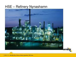
CONTROL SYSTEM • The purpose of this section is to give a general explanation of how the control system works. • Process variables, that determine a good operation of the Unit, play a different role depending upon the type of operation.
MAIN CONTROL LOOPS OF AMINE REGENERATOR AND SOUR WATER STRIPPER SECTIONS • RICH AMINE FLASH DRUM PRESSURE • REGENERATOR REFLUX DRUM PRESSURE • STEAM FLOWRATE TO STRIPPER REBOILER • SOUR WATER STRIPPER PRESSURE • SOUR WATER STRIPPER TEMPERATURE • SOUR WATER FEED SURGE DRUM PRESSURE
RICH AMINE FLASH DRUM PRESSURE With the purpose to avoid amine degradation caused by the oxidation of the DEA solution coming into contact with air, inert gas blanketing facilities are provided. The pressure in the drum is controlled by the pressure controller PIC-1001 acting on two control valves: vent gas valve PV-1001A and inert gas valve PV-1001B.
RICH AMINE FLASH DRUM PRESSURE Split range valves Some control loops have two control valves controlled by one controller. A plot shows the valve position versus controller output. Provide 5% deadband to prevent simultaneous pressuring and venting.
REGENERATOR REFLUX DRUM PRESSURE The pressure in the drum is controlled by the pressure controller PIC-1005 acting on two control valves: PV-1005A located on the line that leads acid gas to SRU Section and PV-1005B located on the line to acid flare.
REGENERATOR REFLUX DRUM PRESSURE Split range valves Provide 5% deadband to prevent system malfunction.
STEAM FLOWRATE TO STRIPPER REBOILER The higher is the flowrate of sour water fed to the stripper, the higher the saturated steam flowrate to the Reboiler must be. The steam flow rate to the Stripper Reboiler is controlled on the basis of the measured flow of the spur water solution entering the Stripper column. The flowrate of SW to the column is regulated by the flow controller FIC located on the discharge line of Stripper Feed Pump, that acts on the flow valve FV located on the column feed stream and that receives a signal from the level controller LIC located on Sour Water Feed Surge Drum. The stripping steam is generated in the Stripper Reboiler by means of LP Steam, whose flow is controlled by the flow controller FIC-2019 acting on FV on the LP Steam line. The FIC-2019 set point is resetted by the signal coming from FIC-2002.
SOUR WATER STRIPPER PRESSURE The overhead pressure in the column is controlled by the pressure controller PIC-2002 acting on two control valves: PV-2002A located on the line that leads acid gas to SRU Section and PV-2002B located on the line to acid flare.
SOUR WATER STRIPPER PRESSURE Split range valves Provide 5% deadband to prevent system malfunction.
SOUR WATER STRIPPER TEMPERATURE The overhead pressure in the stripper sets the stripped water temperature in the stripper bottom at the right value, so as to obtain a good performance. The overhead temperature in the Stripper is controlled by TIC-2007, which resets the flow controller FIC-2007 acting on the flow valve FV-2007 on the delivery line of the Stripper Pumparound Pump.
SOUR WATER STRIPPER TEMPERATURE Split range valves Provide 5% deadband to prevent system malfunction.
SOUR WATER FEED SURGE DRUM PRESSURE The pressure in the drum is controlled by the pressure controller PIC-2001 acting on two control valves: PV-2001A located on the inert gas line and PV-2001B located on the line to acid flare.
SOUR WATER FEED SURGE DRUM PRESSURE Split range valves Provide 5% deadband to prevent simultaneous pressuring and discharging.
LOGIC SYSTEM What is the LOGIC SYSTEM? A Logic System is an integrated highly automated safety facility, able to perform several actions: Handling all the start-up and shut-down phases of the Plant; Isolate the whole plant, one unit of the plant from the other, or just a section of one unit; Interact with the DCS system; Keep always the Plant under safe conditions.
LOGIC SYSTEM HOW DOES IT WORK? The working principle of a Logic System is: INPUT: Upset signal from the Plant OUTPUT: One or more actions performed automatically on valves, equipment, … MAIN FUNCTIONS OF A LOGIC SYSTEM • Shut-Down Procedure • Start-Up Procedure • Avoid Upset conditions during normal operation that could damage the personnel or the equipment
LOGIC SYSTEM MAIN FEATURES OF LOGIC SYSTEM All the logics are handled by a central hardware called PLC (programmable logic control) Input/output signals of PLC are usually electrical, not digital. PLC input signals: output signals from instrumentation installed in the plant. PLC output signals: input signals for SD, ESD, control valves.
LOGIC SYSTEM – START UP • When starting-up a section of a plant, the logic system shall strictly follow a well determined procedure. • This procedure is tied to verify the necessary conditions, in order to guarantee the safety of the operation. • These conditions are called PERMISSIVES.
PERMISSIVE DURING START-UP • HOW IS A START-UP PERFORMED? • Start-up is guided and monitored by well competent operators and specialist engineers. • Start-up must be performed both from field and control room. • The operators in control room shall monitor the start-up via graphic pages.
PERMISSIVE DURING START-UP • On the graphic pages, the whole plant is graphically represented: • - Equipment • - Instruments • - SD, ESD, control valves • - Control loops • - Alarms and SD causes • Furthermore, in the graphic pages the operator can check if all the logic conditions necessary for the start-up are met. • If some of the required permissives are not met, the logic system doesn’t give its permission to start-up.
CAUSE & EFFECT DIAGRAM • The protective system (ESD) shall be based on the input (causes) and the output (effects) as shown in the Cause & Effect Chart
RomeViale Castello della Magliana 7500148 - ItalyPh. +39 06 602161Fax +39 06 65793002info@tecnimontkt.it – www.tecnimontkt.it