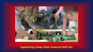
Solar Powered Golf Cart
Solar Powered Golf Cart. Group 9. With Support from:. Jake Bettis Jacob Krueger Matthew Roland Matt Tourtelot. Motivation.


Solar Powered Golf Cart
E N D
Presentation Transcript
Solar Powered Golf Cart Group 9 With Support from: Jake Bettis Jacob Krueger Matthew Roland Matt Tourtelot
Motivation • Rapid growth in renewable energy, such as solar power, has caused a huge increase in the demand for engineers that know how to utilize these alternative sources of energy • With our project we are able to design and create an environmentally friendly vehicle while gaining first-hand knowledge and experience in a growing industry
Goals To create an energy efficient golf cart that is capable of running on solar power and external outlet. A touch-screen display will give the user options for different energy modes, navigational help, and status of golf cart
Objectives • Harvest energy from sunlight to power electric motor and onboard electronic systems • Three modes of energy operations • standard, max performance, max efficiency • Power monitoring system to display battery levels and check for battery storage defects • User touch-screen display • Provides navigational map interface • Allows users to change cart’s operating mode • Displays cart’s current speed, current mode, and battery charge remaining.
Objectives Energy Modes • Standard mode: A normal acceleration ramp will be used for this setting • Max Performance: The motor controller will ramp up the speed almost instantly • Max Efficiency: The motor controller will ramp up the speed very slowly • The biggest power drain on the cart is acceleration so this was controlled to save energy
Specifications and Requirements • Must have a top speed of at least 15 mph • Must have 3 modes of operation which can be controlled by user • Must run off of a 36V or 48V battery storage bank • Batteries must be able to charge from solar panels or wall outlet • Must have atouch-screen display for user information • Must provide navigational aid to user • Must provide power mode options and current speed
Power System Components • Solar Panels and Wall Outlet • provide power for motor and onboard electronics • Solar Charge Controller • Regulate power inputs from solar panels the batteries • Implement MPPT algorithm to keep from overcharging and damaging the batteries • Battery Bank • provides 36V battery supply
Power System Overview Touchscreen Display 5V DC/DC Regulator Wall Outlet Oddroid C1 Motor Battery Bank +36 V Power Board Solar Charge Controller Solar Panels 3.3V DC/DC Regulator Motor Controller
Solar Panel Electrical Specs Project design implements two panels connected in series. *Specs are based on single panel at standard test conditions
Battery Supply • 36V battery bank that will power motor and all onboard electronics • Flooded lead-acid, deep cycle batteries • Able to withstand deep discharge cycles and have a long lifetime • At 25A output batteries can last for 474 minutes, and 122 minutes at 75A
Battery Specs U.S. 2200-XC2 Deep Cycle Lead-Acid battery
Battery Specs • Rate of discharge • Batteries need to be able to operate for as long as possible while supporting different energy modes • Consider current vs. discharge time
Charge Controller • Goal is to regulate voltage and current from solar panels to the battery, to prevent overcharging • Will implement a maximum power point tracking (MPPT) algorithm • Finds the maximum power point on the I/V curve and tracks that point as sunlight conditions vary • Works as DC to DC converter • Outputs GPS coordinate information to the microcomputer • Design is based off of Texas Instruments TIDA-00120
Solar Charge Controller Schematic • Block diagram of Solar Charge Controller System • SM72295: Photovoltaic Full Bridge Driver • INA271 : voltage output, current sense amplifier
Solar Charge Controller Schematic • MSP430F5132: ultra-low power mixed signal microcontroller • LM5019: 100V buck regulator • TLV70433: low dropout regulator (LDO)
MPPT Algorithm • Perturb and Observe • Method is to modify the operating voltage or current from PV panel until you obtain maximum power from it
Touchscreen Display System Objectives • Provide users with straightforward navigation around the UCF campus via GPS location • Navigational map will be interactive and contain certain customizable features • Display the golf cart’s current speed and operating mode • Allow users to easily switch between available cart operating modes
Touchscreen Display System Components • Microcomputer • Provides platform for Android Operating System • Processes GPS and display signal input and output • GPS PCB module • Outputs GPS coordinate information to the microcomputer • Touchscreen Display • Provides user with display of the Android Application • Supplies microcomputer with user input
ODROID C1 Features Implemented • Android Runtime Environment compatibility • Allows for the creation of a specialized Android Application • Easy Debugging • HDMI video signal output • Allows video signal to be sent to the touch screen display while freeing up the USB input for the touch screen’s user input signals
MTK3339 GPS Module • Sends GPS data pertaining to the current user position to the ODROID C1 • 10 Hz update frequency • Accurate to about 3 meters
Android Application Development • Developed within the Eclipse IDE using the latest Android SDK • Many other inherent features of Java are used throughout the application design • Tested for accuracy and reliability on every design prototype iteration
UCF EzNAV Main Menu • Very simple, intuitive interface • The only screen that gives access to every created class • Each button takes the user to a new screen within the app
Navigate Screen • Interactive Google Maps Fragment • “My Location” button and functionality • Map markers for reference and building information • License key for Google Maps API obtained through Google Inc.
Cart Status Screen • Features updating data fields for cart information • Uses signals from the Motor Controller and GPS module to generate values • Interface buttons that allow users to change the cart’s operating mode
Motor Controller Overview • Pre-charge circuit prevents inrush current to motor controller • Potentiometer pedal provides a voltage from 1.45-1.92 • Direction switch removes need for H-Bridge
Power Board Schematic Capacitance Flyback diodes • High current MOSFET’s • On-Resistance of 1.45mΩ
Pedal • Potentiometer over ITS
Modes of Operation • Mode determined by user from touch screen