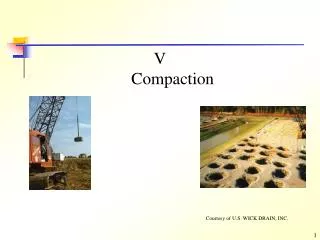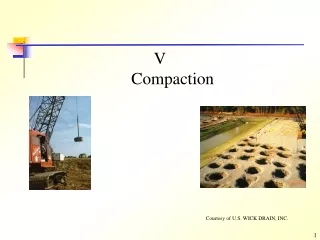

Vibro Compaction
E N D
Presentation Transcript
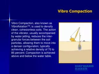
Vibro Compaction Vibro Compaction, also known as VibroflotationTM, is used to densify clean, cohesionless soils. The action of the vibrator, usually accompanied by water jetting, reduces the inter-granular forces between the soil particles, allowing them to move into a denser configuration, typically achieving a relative density of 70 to 85 percent. Compaction is achieved above and below the water table.
Vibro CompactionProfile of Sand Grains Volume reduction due to densification of non-cohesive soils may result in surface settlement of 5% to 15% of the treated depth.
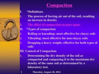
Vibro Compaction Design Considerations • The design approach for Vibro technologies will generally be governed by one or more of the three major categories of site improvement: • Shear resistance increase • Settlement control • Liquefaction & lateral spreading mitigation
Vibro Compaction Design Requirements • Design of the Vibro program requires information on: • Total loads (structure, surcharge, live, wind and seismic) • Soil type (variation, stratigraphy, groundwater location) • Type of footing/slab design • Structural settlement tolerance • Site restrictions and limitations • To address the above issues, the Vibro program is designed such that the zone of influence of the vibratory probe ensures the necessary soil densification and/or reinforcement.
Vibro Compaction Design Steps 1. Perform site investigation Soil gradation important 2. Calculate performance with existing soil conditions Problem understood 3. Establish compaction requirements Sufficient densification to reduce settlement and/or prevent liquefaction 4. Develop appropriate Vibro Compaction approach Treat entire site or just footing? 5. Establish testing criteria Relative density, SPT, CPT, PMT, etc.
Vibro Compaction Increased Bearing Capacity Bearing capacity is a function of the soil’s shear strength which is derived from the soil’s angle of internal friction (f) and/or cohesion (c). The Vibro systems increase the allowable bearing capacity by increasing the effective f angle. Vibro Compaction densifies cohesionless granular soils, thus increasing the angle of internal friction directly. The allowable bearing capacity is calculated with conventional procedures using the improved angle.
Vibro Compaction Reduced Settlement Settlement is a function of the soil’s modulus and consolidation character. Vibro systems decrease the settlement that will occur beneath a proposed foundation by either directly increasing the in situ soil’s modulus value and/or by constructing high modulus Vibro stone columns in a grid pattern beneath the planned foundation. Vibro Compaction densifies cohesionless granular soils, thus increasing the soil’s modulus value directly. The settlement is calculated with conventional procedures using the improved modulus value.
Vibro Compaction Quality Control • Compaction point locations • Resistance level as measured by amp meter (vibrator draws more current in denser soils) • Quantity of fill added or reduction in site level
Vibro Compaction Acceptance Testing • Standard Penetration Test (SPT) • Cone Penetrometer Test (CPT) • Pressuremeter Test (PMT) • Dilatometer Test (DMT) • Load test
Vibro CompactionBenefits • Increases bearing capacity and reduces foundation size • Reduces foundation settlement • Mitigates liquefaction potential • Permits construction on granular fills
Vibro ReplacementStone Columns Vibro Replacement Stone Columns extends the range of soils that can be improved by vibratory techniques to include cohesive soils. Densification and/or reinforcement of the soil with compacted granular columns or “stone columns” is accomplished.
Vibro ReplacementStone Columns Cohesive, mixed and layered soils generally do not densify easily when subjected to vibration alone. The Vibro Replacement Stone Columns technique was developed specifically for these soils, effectively extending the range of soil types that can be improved with the deep vibratory process. With Vibro Replacement Stone Columns, columns of dense, crushed stone are designed to increase bearing capacity, reduce settlement, aid densification and mitigate the potential for liquefaction, and improve shear resistance.
Vibro ReplacementStone Column Construction The two primary methods of Vibro Stone Column construction are: Wet, Top Feed Method (Replacement and Displacement) In this technique, jetting water is used to remove soft material, stabilize the probe hole, and ensure that the stone backfill reaches the tip of the vibrator. This is the most commonly used and most cost-efficient of the deep vibratory methods. However, handling of the spoil generated by the process may make this method more difficult to use on confined sites or in environmentally sensitive areas.
Vibro Replacement Dry, Bottom Feed Method (Displacement) This technique uses the same vibrator probes as standard Vibro Replacement Stone Columns, but with the addition of a hopper and supply tube to feed the stone backfill directly to the tip of the vibrator. Bottom Feed Vibro Replacement is a completely dry operation where the vibrator remains in the ground during the construction process. The elimination of flushing water in turn eliminates the generation of spoil, extending the range of sites that can be treated. Treatment is possible up to a depth of 80 feet and is not inhibited by the presence of groundwater.
Vibro Replacement Design Steps 1. Perform site investigation Soil type, gradation, consolidation, and strength important 2. Calculate predicted improvement Problem understood 3. Establish requirements of ground improvement What settlements, factor of safety, etc., are allowable 4. Design Vibro Replacement scheme Number of stone columns and/or performance requirements required to achieve desired results 5. Establish testing criteria Load test, SPT, area of stone columns
Vibro Replacement Important Parameters • Ground conditions • Relative density • Degree of saturation • Permeation
Vibro ReplacementDesign Considerations • The design approach for Vibro technologies will generally be governed by one or more of the three major categories of site improvement: • Shear resistance increase • Settlement control • Liquefaction & lateral spreading mitigation
Vibro ReplacementDesign Requirements Design of the Vibro program requires information on: • Total loads (structure, surcharge, live, wind and seismic) • Soil type (variation, stratigraphy, groundwater location) • Type of footing/slab design • Structural settlement tolerance • Site restrictions and limitations To address the above issues, the Vibro program is designed such that the zone of influence of the vibratory probe ensures the necessary soil densification and/or reinforcement.
Vibro Replacement Increased Bearing Capacity Vibro Replacement constructs dense, Vibro stone columns in the zone requiring improvement. The allowable bearing capacity can be calculated by a variety of methods, such as the one developed by Priebe in “The Design of Vibro Replacement”, Ground Engineering, December 1995. If any of the in situ soils are granular, their improved value should also be accounted for in the design.
Vibro Replacement Reduced Settlement Vibro Replacement constructs high modulus dense Vibro stone columns in the zone requiring improvement. The anticipated settlement can be evaluated by a variety of methods, such as the Priebe method. This method provides an improvement factor based on the stone column’s angle of internal friction and the percentage of the treatment zone replaced by stone (area replacement ratio). In addition, if any of the in situ soils are granular, their improved parameters should also be included in the design.
Vibro ReplacementReduced Settlement Method to estimate settlement reduction using stone columns in cohesive soils
Vibro ReplacementLiquefaction Prevention • Seismic motion causes pore pressure to increase. When the pore pressure increases to equal interstitial grain-to-grain stresses, liquefaction is initiated. The soil then loses shear strength, resulting in bearing failures and slope instability, followed by large deformations (horizontal and vertical) • Site improvement by densification has proven to be the most effective solution. Densification will increase interstitial stresses, thus preventing liquefaction and settlement • Densification is required to preclude excessive settlements and offers the most secure remedy to multiple ground accelerations (aftershocks)
Vibro ReplacementEmbankment Subgrade Improvement Vibro stone columns increase the slope stability safety factor especially when they attract sufficient loading to increase shearing resistance. The shear strength of treated soil depends on the shear strength of the untreated soil, the transverse shear strength of the columns, the area replacement ratio and the load conditions.
Vibro Replacement Quality Control Production Monitoring • Quantity and quality of backfill added • Vibrator amperage draw • Treatment depth Post-Construction Testing • Standard Penetration Testing (SPT) • Cone Penetrometer Testing (CPT) • Dilatometer Testing (DMT) • Load Testing • Shear Wave Velocity Profiling
Vibro Replacement Benefits • Permits shallow footing construction • Reduces foundation settlement • Increases bearing capacity, allowing reduction in footing size • Mitigates liquefaction potential • Prevents earthquake-induced lateral spreading • Provides slope stabilization • Permits construction on fills
Dynamic Compaction Weights of 10 to 30 tons Drop heights of 50 to 100 ft Impact grids of 7 x 7 ft to 20 x 20 ft