Download

1 / 38
760 likes | 1.65k Vues
Projection of point and line. NOTATIONS. FOLLOWING NOTATIONS SHOULD BE FOLLOWED WHILE NAMEING DIFFERENT VIEWS IN ORTHOGRAPHIC PROJECTIONS. OBJECT POINT A LINE AB. IT’S TOP VIEW a a b.

E N D
Projection of point and line engineering108.com
NOTATIONS FOLLOWING NOTATIONS SHOULD BE FOLLOWED WHILE NAMEING DIFFERENT VIEWS IN ORTHOGRAPHIC PROJECTIONS. OBJECT POINT A LINE AB IT’S TOP VIEW a a b IT’S FRONT VIEWa’ a’ b’ IT’S SIDE VIEWa” a” b” SAME SYSTEM OF NOTATIONS SHOULD BE FOLLOWED INCASE NUMBERS, LIKE 1, 2, 3 – ARE USED. engineering108.com
2nd Quadrant VP 1ST Quad. 2nd Quad. 1st Quadrant F.V. Y Observer HP X Y X 3rdQuadrant Observer 4th Quad. 3rd Quad. 4th Quadrant THIS QUADRANT PATTERN, IF OBSERVED ALONG X-Y LINE ( IN RED ARROW DIRECTION) WILL EXACTLY APPEAR AS SHOWN ON RIGHT SIDE AND HENCE, IT IS FURTHER USED TO UNDERSTAND ILLUSTRATION PROPERLLY. engineering108.com
For Tv For Tv For Tv POINT A IN HP & INFRONT OF VP POINT A ABOVE HP & IN VP POINT A ABOVE HP & INFRONT OF VP Y Y For Fv For Fv For Fv X X ORTHOGRAPHIC PRESENTATIONS OF ALL ABOVE CASES. a’ VP VP VP a’ a a’ X Y X Y a X Y a HP HP HP PROJECTIONS OF A POINT IN FIRST QUADRANT. PICTORIAL PRESENTATION PICTORIAL PRESENTATION A a’ a’ A Y a’ a a X A a Fv above xy, Tv below xy. Fv above xy, Tv on xy. Fv on xy, Tv below xy. engineering108.com
VP VP OBSERVER OBSERVER OBSERVER OBSERVER HP HP HP HP VP VP POINT A IN 1ST QUADRANT POINT A IN 2ND QUADRANT Point A is Placed In different quadrants and it’s Fv & Tv are brought in same plane for Observer to see clearly. Fv is visible as it is a view on VP. But as Tv is is a view on Hp, it is rotated downward 900, In clockwise direction.The In front part of Hp comes below xy line and the part behind Vp comes above. Observe and note the process. a’ A A a’ a a a a a’ A a’ A POINT A IN 4TH QUADRANT POINT A IN 3RD QUADRANT engineering108.com
PROJECTIONS OF STRAIGHT LINES. INFORMATION REGARDING A LINE means IT’S LENGTH, POSITION OF IT’S ENDS WITH HP & VP IT’S INCLINATIONS WITH HP & VP WILL BE GIVEN. AIM:- TO DRAW IT’S PROJECTIONS - MEANS FV & TV. SIMPLE CASES OF THE LINE • A VERTICAL LINE ( LINE PERPENDICULAR TO HP & // TO VP) • LINE PARALLEL TO BOTH HP & VP. • LINE INCLINED TO HP & PARALLEL TO VP. • LINE INCLINED TO VP & PARALLEL TO HP. • LINE INCLINED TO BOTH HP & VP. STUDY ILLUSTRATIONS GIVEN ON NEXT PAGE SHOWING CLEARLY THE NATURE OF FV & TV OF LINES LISTED ABOVE AND NOTE RESULTS. engineering108.com
Orthographic Pattern V.P. a’ a’ V.P. b’ Fv A V.P. B b’ a’ Y A b’ X Y Y B Tv a b X X H.P. V.P. Fv a’ b’ b a X Y a b Tv H.P. For Tv Fv is a vertical line Showing True Length & Tv is a point. 1. FV A Line perpendicular to Hp & // to Vp For Fv a b TV Orthographic Pattern Fv & Tv both are // to xy & both show T. L. For Tv 2. A Line // to Hp & // to Vp F.V. For Fv T.V. engineering108.com
V.P. b’ F.V. a’ X Y a b T.V. b’ V.P. a’ V.P. H.P. b’ B F.V. B A V.P. Y a’ Fv a’ b’ b A a b Ø T.V. X a X Y a Ø Tv b H.P. Fv inclined to xy Tv parallel to xy. 3. A Line inclined to Hp and parallel to Vp Orthographic Projections Tv inclined to xy Fv parallel to xy. 4. F.V. A Line inclined to Vp and parallel to Hp Ø T.V. engineering108.com
V.P. b’ FV a’ For Tv For Tv X Y b’ b’ V.P. V.P. a B B F.V. F.V. TV Y Y H.P. a’ a’ b For Fv For Fv A A X X a a b b T.V. T.V. 5. A Line inclined to both Hp and Vp (Pictorial presentation) On removal of object i.e. Line AB Fv as a image on Vp. Tv as a image on Hp, Orthographic Projections Fv is seen on Vp clearly. To see Tv clearly, HP is rotated 900 downwards, Hence it comes below xy. Note These Facts:- Both Fv & Tv are inclined to xy. (No view is parallel to xy) Both Fv & Tv are reduced lengths. (No view shows True Length) engineering108.com
V.P. V.P. V.P. b’ b’ b1’ FV FV a’ a’ a’ 1’ X X Y Y X Y Ø a a TV a TL TV TV Tv H.P. H.P. b1 b b H.P. b Note the procedure When True Length is known, How to locate Fv & Tv. (Component a-1 of TL is drawn which is further rotated to determine Fv) Note the procedure When Fv & Tv known, How to find True Length. (Views are rotated to determine True Length & it’s inclinations with Hp & Vp). Orthographic Projections Means Fv & Tv of Line AB are shown below, with their apparent Inclinations & b’ b1’ Fv TL TL 1 b2 Here a -1 is component of TL ab1 gives length of Fv. Hence it is brought Up to Locus of a’ and further rotated to get point b’. a’ b’ will be Fv. Similarly drawing component of other TL(a’ b1‘) Tv can be drawn. In this sketch, TV is rotated and made // to XY line. Hence it’s corresponding FV a’ b1’Is showing True Length & True Inclination with Hp. Here TV (ab) is not // to XY line Hence it’s corresponding FV a’ b’ is not showing True Length & True Inclination with Hp. engineering108.com
1) True Length ( TL) – a’ b1’ & a b Distance between End Projectors. V.P. 2) Angle of TL with Hp - 3) Angle of TL with Vp – b1’ b’ 4) Angle of FV with xy – 5) Angle of TV with xy – 6) LTV (length of FV) – Component (a-1) Fv TL 7) LFV (length of TV) – Component (a’-1’) 8) Position of A- Distances of a & a’ from xy 1’ 9) Position of B- Distances of b & b’ from xy a’ NOTE this LTV 10) Distance between End Projectors & Construct with a’ X Y LFV a 1 b’ & b1’ on same locus. Ø b & b1 on same locus. Ø & Construct with a TL Tv Also Remember True Length is never rotated. It’s horizontal component is drawn & it is further rotated to locate view. b1 b H.P. Views are always rotated, made horizontal & further extended to locate TL, & Ø The most important diagram showing graphical relations among all important parameters of this topic. Study and memorize it as a CIRCUIT DIAGRAM And use in solving various problems. Important TEN parameters to be remembered with Notations used here onward Ø engineering108.com
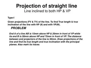
GROUP (A) GENERAL CASES OF THE LINE INCLINED TO BOTH HP & VP ( based on 10 parameters). 1 PROBLEM Line AB is 75 mm long and it is 300 & 400 Inclined to Hp & Vp respectively. End A is 12mm above Hp and 10 mm in front of Vp. Draw projections. Line is in 1st quadrant. b’ b’1 FV TL SOLUTION STEPS: 1) Draw xy line and one projector. 2) Locate a’ 12mm above xy line & a 10mm below xy line. 3) Take 300 angle from a’ & 400 from a and mark TL I.e. 75mm on both lines. Name those points b1’ and b1 respectively. 4) Join both points with a’ and a resp. 5) Draw horizontal lines (Locus) from both points. 6) Draw horizontal component of TL a b1 from point b1 and name it 1. ( the length a-1 gives length of Fv as we have seen already.) 7) Extend it up to locus of a’ and rotating a’ as center locate b’ as shown. Join a’ b’ as Fv. 8) From b’ drop a projector down ward & get point b. Join a & b I.e. Tv. a’ X Y a LFV Ø TV TL b b1 engineering108.com
PROBLEM : Line AB 75mm long makes 450 inclination with Vp while it’s Fv makes 550. End A is 10 mm above Hp and 15 mm in front of Vp.If line is in 1st quadrant draw it’s projections and find it’s inclination with Hp. b’1 b’ LOCUS OF b1’ Solution Steps:- 1.Draw x-y line. 2.Draw one projector for a’ & a 3.Locate a’ 10mm above x-y & Tv a 15 mm below xy. 4.Draw a line 450 inclined to xy from point a and cut TL 75 mm on it and name that point b1 Draw locus from point b1 5.Take 550 angle from a’ for Fv above xy line. 6.Draw a vertical line from b1 up to locus of a and name it 1. It is horizontal component of TL & is LFV. 7.Continue it to locus of a’ and rotate upward up to the line of Fv and name it b’.This a’ b’ line is Fv. 8. Drop a projector from b’ on locus from point b1 and name intersecting point b. Line a b is Tv of line AB. 9.Draw locus from b’ and from a’ with TL distance cut point b1‘ 10.Join a’ b1’ as TL and measure it’s angle at a’. It will be true angle of line with HP. FV TL 550 a’ y X LFV a 1 450 TV TL LOCUS OF b b b1 engineering108.com
PROBLEM - Fv of line AB is 500 inclined to xy and measures 55 mm long while it’s Tv is 600 inclined to xy line. If end A is 10 mm above Hp and 15 mm in front of Vp, draw it’s projections,find TL, inclinations of line with Hp & Vp. b’ b’1 FV TL SOLUTION STEPS: 1.Draw xy line and one projector. 2.Locate a’ 10 mm above xy and a 15 mm below xy line. 3.Draw locus from these points. 4.Draw Fv 500 to xy from a’ and mark b’ Cutting 55mm on it. 5.Similarly draw Tv 600 to xy from a & drawing projector from b’ Locate point b and join a b. 6.Then rotating views as shown, locate True Lengths ab1 & a’b1’ and their angles with Hp and Vp. 500 a’ X y a 600 TL b1 b engineering108.com
SOLUTION STEPS: 1.Draw xy line and one projector. 2.Locate a’ 10 mm above xy and a 15 mm below xy line. 3.Draw locus from these points. 4.Cut 60mm distance on locus of a’ & mark 1’ on it as it is LTV. 5.Similarly Similarly cut 50mm on locus of a and mark point 1 as it is LFV. 6.From 1’ draw a vertical line upward and from a’ taking TL ( 75mm ) in compass, mark b’1 point on it. Join a’ b’1 points. 7. Draw locus from b’1 8. With same steps below get b1 point and draw also locus from it. 9. Now rotating one of the components I.e. a-1 locate b’ and join a’ with it to get Fv. 10. Locate tv similarly and measure Angles & PROBLEM :- Line AB is 75 mm long .It’s Fv and Tv measure 50 mm & 60 mm long respectively. End A is 10 mm above Hp and 15 mm in front of Vp. Draw projections of line AB if end B is in first quadrant. Find angle with Hp and Vp. b’ b’1 FV TL LTV 1’ a’ X Y LFV a 1 TV TL b1 b engineering108.com
SOLUTION STEPS: 1.Draw xy line and one projector. 2.Locate c’ on xy and c 50mm below xy line. 3.Draw locus from these points. 4.Draw locus of d 15 mm below xy 5.Cut 50mm & 75 mm distances on locus of d from c and mark points d & d1 as these are Tv and line CD lengths resp.& join both with c. 6.From d1 draw a vertical line upward up to xy I.e. up to locus of c’ and draw an arc as shown. 7 Then draw one projector from d to meet this arc in d’ point & join c’ d’ 8. Draw locus of d’ and cut 75 mm on it from c’ as TL 9.Measure Angles & PROBLEM :- T.V. of a 75 mm long Line CD, measures 50 mm. End C is in Hp and 50 mm in front of Vp. End D is 15 mm in front of Vp and it is above Hp. Draw projections of CD and find angles with Hp and Vp. LOCUS OFd’ & d’1 d’ d’1 FV TL c’ Y X LOCUS OFd & d1 d1 d TL TV c engineering108.com
GROUP (B) PROBLEMS INVOLVING TRACES OF THE LINE. TRACES OF THE LINE:- THESE ARE THE POINTS OF INTERSECTIONS OF A LINE ( OR IT’S EXTENSION ) WITH RESPECTIVE REFFERENCE PLANES. A LINE ITSELF OR IT’S EXTENSION, WHERE EVER TOUCHES H.P., THAT POINT IS CALLED TRACE OF THE LINE ON H.P.( IT IS CALLED H.T.) SIMILARLY, A LINE ITSELF OR IT’S EXTENSION, WHERE EVER TOUCHES V.P., THAT POINT IS CALLED TRACE OF THE LINE ON V.P.( IT IS CALLED V.T.) V.T.:- It is a point on Vp. Hence it is called Fv of a point in Vp. Hence it’s Tv comes on XY line.( Here onward named as v ) H.T.:- It is a point on Hp. Hence it is called Tv of a point in Hp. Hence it’s Fv comes on XY line.( Here onward named as ’h’ ) engineering108.com
b’ FV a’ y x a TV b Observe & note :- 1. Points h’ & v always on x-y line. 2. VT’ & v always on one projector. 3. HT & h’ always on one projector. 4. FV - h’- VT’ always co-linear. 5. TV - v - HT always co-linear. STEPS TO LOCATE HT. (WHEN PROJECTIONS ARE GIVEN.) • Begin with FV. Extend FV up to XY line. • Name this point h’ ( as it is a Fv of a point in Hp) 3. Draw one projector from h’. 4. Now extend Tv to meet this projector. This point is HT v h’ HT VT’ STEPS TO LOCATE VT. (WHEN PROJECTIONS ARE GIVEN.) • Begin with TV. Extend TV up to XY line. • Name this point v ( as it is a Tv of a point in Vp) 3. Draw one projector from v. 4. Now extend Fv to meet this projector. This point is VT engineering108.com
PROBLEM :- Fv of line AB makes 450 angle with XY line and measures 60 mm. Line’s Tv makes 300 with XY line. End A is 15 mm above Hp and it’s VT is 10 mm below Hp. Draw projections of line AB,determine inclinations with Hp & Vp and locate HT, VT. b’1 b’ SOLUTION STEPS:- Draw xy line, one projector and locate fv a’ 15 mm above xy. Take 450 angle from a’ and marking 60 mm on it locate point b’. Draw locus of VT, 10 mm below xy & extending Fv to this locus locate VT. as fv-h’-vt’ lie on one st.line. Draw projector from vt, locate v on xy. From v take 300 angle downward as Tv and it’s inclination can begin with v. Draw projector from b’ and locate b I.e.Tv point. Now rotating views as usual TL and it’s inclinations can be found. Name extension of Fv, touching xy as h’ and below it, on extension of Tv, locate HT. a’ 450 15 v x y h’ 300 10 HT VT’ a b b1 engineering108.com
10 30 45 PROBLEM One end of line AB is 10mm above Hp and other end is 100 mm in-front of Vp. It’s Fv is 450 inclined to xy while it’s HT & VT are 45mm and 30 mm below xy respectively. Draw projections and find TL with it’s inclinations with Hp & VP. b’ b’1 LOCUS OF b’ & b’1 FV TL 450 a’ v h’ Y X SOLUTION STEPS:- Draw xy line, one projector and locate a’ 10 mm above xy. Draw locus 100 mm below xy for points b & b1 Draw loci for VT and HT, 30 mm & 45 mm below xy respectively. Take 450 angle from a’ and extend that line backward to locate h’ and VT, & Locate v on xy above VT. Locate HT below h’ as shown. Then join v – HT – and extend to get top view end b. Draw projector upward and locate b’ Make a b & a’b’ dark. Now as usual rotating views find TL and it’s inclinations. VT’ HT 100 a TL TV b b1 LOCUS OF b & b1 engineering108.com
b’ b1’ FV TL a’ & v X Y & VT’ a TV b Instead of considering a & a’ as projections of first point, if v & VT’ are considered as first point , then true inclinations of line with Hp & Vp i.e. angles & can be constructed with points VT’ & V respectively. Then from point v & HT angles can be drawn. & From point VT’ & h’ angles can be drawn. TL engineering108.com b1
b1’ b’ FV a’ a1’ X Y b1 a a1 TV b PROBLEM :- Line AB 100 mm long is 300 and 450 inclined to Hp & Vp respectively. End A is 10 mm above Hp and it’s VT is 20 mm below Hp .Draw projections of the line and it’s HT. 100 mm Locus of a & a1’ SOLUTION STEPS:- Draw xy, one projector and locate on it VT and V. Draw locus of a’ 10 mm above xy. Take 300 from VT and draw a line. Where it intersects with locus of a’ name it a1’ as it is TL of that part. From a1’ cut 100 mm (TL) on it and locate point b1’ Now from v take 450 and draw a line downwards & Mark on it distance VT-a1’ I.e.TL of extension & name it a1 Extend this line by 100 mm and mark point b1. Draw it’s component on locus of VT’ & further rotate to get other end of Fv i.e.b’ Join it with VT’ and mark intersection point (with locus of a1’ ) and name it a’ Now as usual locate points a and b and h’ and HT. 10 v h’ (450) 20 (300) VT’ HT 100 mm engineering108.com
b1’ b’ FV a’ a1’ h’ X Y HT b1 a a1 TV b PROBLEM :- A line AB is 75 mm long. It’s Fv & Tv make 450 and 600 inclinations with X-Y line resp End A is 15 mm above Hp and VT is 20 mm below Xy line. Line is in first quadrant. Draw projections, find inclinations with Hp & Vp. Also locate HT. 75 mm Locus of a & a1’ 15 v 600 20 450 VT’ SOLUTION STEPS:- Similar to the previous only change is instead of line’s inclinations, views inclinations are given. So first take those angles from VT & v Properly, construct Fv & Tv of extension, then determine it’s TL( V-a1) and on it’s extension mark TL of line and proceed and complete it. 75 mm engineering108.com
b1’ b’ FV 75mm a’ 15 v X Y 20 25 VT’ a TV b PROBLEM :- The projectors drawn from VT & end A of line AB are 40mm apart. End A is 15mm above Hp and 25 mm in front of Vp. VT of line is 20 mm below Hp. If line is 75mm long, draw it’s projections, find inclinations with HP & Vp a1’ Draw two projectors for VT & end A Locate these points and then 40mm b1 engineering108.com
Line AB is in AIP as shown in above figure no 1. It’s FV (a’b’) is shown projected on Vp.(Looking in arrow direction) Here one can clearly see that the Inclination of AIP with HP = Inclination of FV with XY line b’ A.I.P. a’ B A X A.V.P. a b GROUP (C) CASES OF THE LINES IN A.V.P., A.I.P. & PROFILE PLANE. A B Line AB is in AVP as shown in above figure no 2.. It’s TV (a b) is shown projected on Hp.(Looking in arrow direction) Here one can clearly see that the Inclination of AVP with VP = Inclination of TV with XY line engineering108.com
For T.V. VP PP a’ b’ For F.V. a HP b Results:- 1. TV & FV both are vertical, hence arrive on one single projector. 2. It’s Side View shows True Length ( TL) 3. Sum of it’s inclinations with HP & VP equals to 900 ( 4. It’s HT & VT arrive on same projector and can be easily located From Side View. + = 900 ) LINE IN A PROFILE PLANE ( MEANS IN A PLANE PERPENDICULAR TO BOTH HP & VP) ORTHOGRAPHIC PATTERN OF LINE IN PROFILE PLANE VT a” a’ A FV LSV b” b’ Y X HT a B TV b engineering108.com
b1’ Locus of b’ a1’ 15 X Y 450 10 AVP 450 to VP b b1 PROBLEM - Line AB 80 mm long, makes 300 angle with Hp and lies in an Aux.Vertical Plane 450 inclined to Vp. End A is 15 mm above Hp and VT is 10 mm below X-y line. Draw projections, fine angle with Vp and Ht. b’ Locus of a’ & a1’ a’ h’ v HT VT a Simply consider inclination of AVP as inclination of TV of our line, well then? Locus of b’ engineering108.com
X Y PROBLEM :- A line AB, 75mm long, has one end A in Vp. Other end B is 15 mm above Hp and 50 mm in front of Vp.Draw the projections of the line when sum of it’s Inclinations with HP & Vp is 900, means it is lying in a profile plane. Find true angles with ref.planes and it’s traces. SOLUTION STEPS:- After drawing xy line and one projector Locate top view of A I.e point a on xy as It is in Vp, Locate Fv of B i.e.b’15 mm above xy as it is above Hp.and Tv of B i.e. b, 50 mm below xy asit is 50 mm in front of Vp Draw side view structure of Vp and Hp and locate S.V. of point B i.e. b’’ From this point cut 75 mm distance on Vp and Mark a’’ as A is in Vp. (This is also VT of line.) From this point draw locus to left & get a’ Extend SV up to Hp. It will be HT. As it is a Tv Rotate it and bring it on projector of b. Now as discussed earlier SV gives TL of line and at the same time on extension up to Hp & Vp gives inclinations with those panes. VT (VT) a” a’ Side View ( True Length ) Front view VP b” b’ (HT) a HP top view b HT engineering108.com
APPLICATIONS OF PRINCIPLES OF PROJECTIONS OF LINES IN SOLVING CASES OF DIFFERENT PRACTICAL SITUATIONS. In these types of problems some situation in the field or some object will be described . It’s relation with Ground ( HP ) And a Wall or some vertical object ( VP ) will be given. Indirectly information regarding Fv & Tv of some line or lines, inclined to both reference Planes will be given and you are supposed to draw it’s projections and further to determine it’s true Length and it’s inclinations with ground. Here various problems along with actual pictures of those situations are given for you to understand those clearly. Now looking for views in given ARROW directions, YOU are supposed to draw projections & find answers, Off course you must visualize the situation properly. CHECK YOUR ANSWERS WITH THE SOLUTIONS GIVEN IN THE END. ALL THE BEST !! engineering108.com
PROBLEM --Two objects, a flower (A) and an orange (B) are within a rectangular compound wall, whose P & Q are walls meeting at 900. Flower A is 1M & 5.5 M from walls P & Q respectively. Orange B is 4M & 1.5M from walls P & Q respectively. Drawing projection, find distance between them If flower is 1.5 M and orange is 3.5 M above the ground. Consider suitable scale.. TV Wall Q B Wall P A FV engineering108.com
PROBLEM :- Two mangos on a tree A & B are 1.5 m and 3.00 m above ground and those are 1.2 m & 1.5 m from a 0.3 m thick wall but on opposite sides of it. If the distance measured between them along the ground and parallel to wall is 2.6 m, Then find real distance between them by drawing their projections. TV B 0.3M THICK A FV engineering108.com
PROBLEM -oa, ob & oc are three lines, 25mm, 45mm and 65mm long respectively.All equally inclined and the shortest is vertical.This fig. is TV of three rods OA, OB and OC whose ends A,B & C are on ground and end O is 100mm above ground. Draw their projections and find length of each along with their angles with ground. TV O 65 mm C 25mm A FV 45 mm B engineering108.com
N S W PROBLEM : A person observes two objects, A & B, on the ground, from a tower, 15 M high, At the angles of depression 300 & 450. Object A is is due North-West direction of observer and object B is due West direction. Draw projections of situation and find distance of objects from observer and from tower also. O 300 450 A B engineering108.com
PROBLEM :-Guy ropes of two poles fixed at 4.5m and 7.5 m above ground, are attached to a corner of a building 15 M high, make 300 and 450 inclinations with ground respectively.The poles are 10 M apart. Determine by drawing their projections,Length of each rope and distance of poles from building. TV C 15 M 300 A 4.5 M 450 B FV 10 M 7.5M engineering108.com
4 M 1.2 M 0.7 M PROBLEM :- A tank of 4 M height is to be strengthened by four stay rods from each corner by fixing their other ends to the flooring, at a point 1.2 M and 0.7 M from two adjacent walls respectively, as shown. Determine graphically length and angle of each rod with flooring. TV FV engineering108.com
TV Hook 5 M D A C 2 M 1.5 M FV B PROBLEM :- A horizontal wooden platform 2 M long and 1.5 M wide is supported by four chains from it’s corners and chains are attached to a hook 5 M above the center of the platform. Draw projections of the objects and determine length of each chain along with it’s inclination with ground. H engineering108.com
PROBLEM :- A PICTURE FRAME 2 M WIDE AND 1 M TALL IS RESTING ON HORIZONTAL WALL RAILING MAKES 350 INCLINATION WITH WALL. IT IS ATTAACHED TO A HOOK IN THE WALL BY TWO STRINGS. THE HOOK IS 1.5 Ma ABOVE WALL RAILING. DETERMINE LENGTH OF EACH CHAIN AND TRUE ANGLE BETWEEN THEM TV 350 1.5 M 1 M FV 2 M Wall railing engineering108.com
Thank You For more tutorials on engineering subjects visit is at engineering108.com engineering108.com