Download
1 / 41
410 likes | 604 Vues
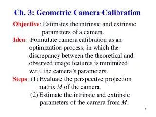
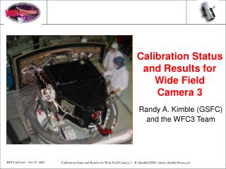
Calibration Status and Results for Wide Field Camera 3. Randy A. Kimble (GSFC) and the WFC3 Team. Outline. Purpose/potential of WFC3 Configuration of instrument Ambient and thermal-vac calibration results Improvements in work – filters, crosstalk, IR detector

E N D
Calibration Status and Results for Wide Field Camera 3 Randy A. Kimble (GSFC) and the WFC3 Team
Outline • Purpose/potential of WFC3 • Configuration of instrument • Ambient and thermal-vac calibration results • Improvements in work – filters, crosstalk, IR detector • Future calibration plans
Key Team MembersSupporting Calibration • WFC3 also supported by Science Oversight Committee, chaired by Bob O’Connell/University of Virginia
Origins/Purpose of WFC3 • WFC3 originated when HST’s nominal observing lifetime was first extended from 2005 to 2010: facility instrument conceived for installation during Servicing Mission 4, to extend and enhance HST’s imaging capability • If SM4 approved, era of WFC3 operation now likely to be late 2007/2008 2013 and beyond? • WFC3 has been designed as a powerful general purpose camera: • widest spectral coverage of any HST instrument • 200-1000 nm in UVIS channel; 850-1700 nm in IR channel • complementary to ACS
Key Aspects of WFC3 • Unique capabilities in the near-UV • 200 to 400 nm • Unique capabilities in the near-IR – without cryogen or mechanical cryocooler! • 850 to 1700 nm (though warm, HST is very powerful in this range) • Large and diverse set of filters and grisms: 63 UVIS, 16 IR • Very capable accompaniment to ACS in the red, with more filters, fresh start with respect to radiation damage, and greater tolerance of CTE degradation
WFC3’s Intended Destination WFC3 is intended to replace the extraordinarily successful but aging WFPC2 in its radial instrument bay.
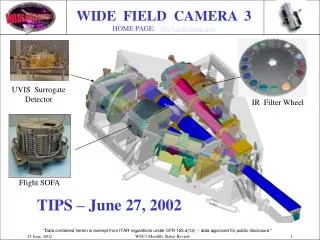
Overall WFC3 Configuration B-Latch Dimensions: 7.5’ x 7’ x 3’ Weight: 907 lbs
UVIS Channel Summary • Key Properties • 200 – 1000 nm • 4K x 4K CCD mosaic (two 2K x 4K UV-optimized CCDs) • 0.04” x 0.04” pixels, 160” x 160” field of view • The WFC3 UVIS channel will extend high-sensitivity, large-format imaging at HST’s sharp angular resolution to the near UV. Relative fields of view of HST’s NUV imagers
NUV Observations Probe Age of Stellar Populations UVIS Channel Science Goals • The UVIS channel will be particularly well suited to the study of: • Star formation history of galaxies (see figure at right) • Chemical enrichment history of galaxies • Ly dropouts at z = 1 – 2. • It will also probe one of the darkest spectral regions of the natural sky background (~200 nm).
CCD Detectors • The WFC3 CCDs, developed by Marconi (now e2v) are shown in their flight housing (left) and mounted in the instrument (right). • The end-to-end read noise for the flight CCDs and electronics is 3 e- rms for all four readout amplifiers.
IR Channel Summary • Key Properties • 850 – 1700 nm • 1K x 1K HgCdTe array with 1.7 micron cutoff • 0.13” x 0.13” pixels, 139” x 123” field of view • zodiacal-background-limited sensitivity in broadband filters • The WFC3 IR channel will provide a 10-20+ x increase in survey speed vs. NICMOS + cryocooler, with finer angular resolution and improved stability, photometric accuracy, and cosmetics. Relative fields of view of HST’s IR imagers
IR Color-Color Identification of High-z Galaxies IR Channel Science Goals • The IR channel will take advantage of the dark IR sky in space to study: • Type Ia supernovae and the accelerating universe • High-redshift galaxy formation (high-z dropouts) – note the strong NIR color-color discrimination of high-z galaxies in the figure at right • Sources of cosmic re-ionization • Dust-enshrouded star formation • Water and ices in the solar system.
IR Detectors • The novel 1.7 micron cutoff wavelength of the IR array (left), developed by Rockwell Scientific, permits low-dark-current operation at a temperature of <150 K, achievable with thermo-electric cooling alone. • A cooled inner shield (center) within the detector housing (right) helps to minimize the thermal background radiation incident on the array.
Ambient and Thermal-Vac Calibrations Performed • During “cancellation period” of 2004, instrument was fully integrated in a “non-final” mode, in which a number of hardware issues were tagged as “liens”, but not closed out • We targetted a “performance characterization” in which WFC3’s performance could be demonstrated for the purposes of contemplating non-HST use • Extensive suite of tests and calibrations performed, both in ambient and thermal-vac conditions • Ambient tests of UVIS channel • Thermal-vac tests of both channels – 1st opportunity for end-to-end look at IR channel • Not a full science calibration, but all critical performance issues examined
Thermal/Vac Test Setup Optical Stimulus Cryopanels WFC3 RIAF
Thermal/Vac Performance Highlights • Overall instrument performed very well – never came up to air for an instrument issue • 13,000 images obtained, assessing all aspects of WFC3 performance • Detailed results documented in several dozen Instrument Science Reports • http://www.stsci.edu/hst/wfc3/documents/ISRs • Easy to find: STScI → HST → Instruments → WFC3 → ISRs • Results confirm the powerful performance of WFC3 across its wide spectral range
UVIS Results *Specs apply to performance with OTA. Measurements obtained with CASTLE require corrections for differences in the optical systems. 250nm EE likely to fall just below CEI requirement (~0.72).
250nm 350nm 633nm 810nm Goals Specs UVIS Channel Shows ExcellentEnd-to-End Image Quality 810nm
UVIS System Throughput UVIS throughput very close to or better than predictions
IR Results *Corrections for OTA vs. CASTLE likely to cause 1.0μm core EE to meet CEI spec (~0.60), while 1.6μm core EE likely to fall just below spec (~0.46).
IR Channel Shows ExcellentEnd-to-End Image Quality • Thermal/vac was first opportunity to see IR channel operate end-to-end. Very gratifying to see how well it worked overall. • Below: Image, encircled energy vs. radius at 1 micron wavelength.
WFC3 IR Throughput IR throughput 10-15% below component predictions; this discrepancy is a bit beyond the expected error bars.
Discovery Efficiency (Throughput x FOV) Based on Thermal-Vac Results Curves connect values at central wavelengths of available broadband filters – instruments’ spectral coverage is wider
UVIS Filter Ghosts • Nasty ghost images in a small subset of UVIS filters • Inter-reflections between “air-gap” substrates or coating layers • Excellent replacements in hand for all severe cases; two less critical shipping this week New F225W • Strong field-dependent ghosts in current F225W
New UV Filters Improve Ghost Performance and Increase Sensitivity
Point-Like Filter Ghosts (e.g. F606W) F606W replacement – nearly ghost-free
UVIS Crosstalk Solution In Hand • Electronic crosstalk observed from quadrant to quadrant of 4-amp readout • Analogous to ACS “extended source” crosstalk, but stronger (5-10e) • Source traced to A/D conversion of pixel n while sampling pixel n+1 • Eliminate by speeding up A/D conversion and fitting it into pixel period away from sampling (<0.1e remains) • Validated on non-flight elect.
Radiation-induced background morphology 800 nm flat-field morphology IR FPA Radiation Effect • WFC3 radiation testing revealed a radiation-induced background effect in the IR focal plane arrays • Diffuse background produced, in addition to localized “hits” • Followup testing in May 2004 identified the source as luminescence in the thick CdZnTe substrate on which the HgCdTe detectors are grown
Estimating On-Orbit Impact • Extrapolation to flight situation is very difficult without full understanding of the microphysics of the phenomenon • But making our best estimate, we predict ~0.25 electrons/pixel/second in orbit from the radiation effect • Significant compared with other backgrounds, potentially leading to significant impact on IR channel sensitivity • Estimate is very uncertain, but not a risk we want to take • Fortunately, solution exists: substrate-removed detectors are now available! Fabrication of new IR arrays for WFC3 is underway
Insignificant Background Seen In Substrate-Removed Detector Substrate On Substrate Off • The diffuse radiation-induced background is reduced to undetectable levels when the substrate is removed • Scales to negligible background for the on-orbit case
Dramatic QE Improvement with Substrate Removal QE For Devices With High and Flat QE
Dramatic QE Improvement with Substrate Removal (2) QE For Devices With Sloped QE
Cumulative Dark Distributions Dark Current For Devices With High and Flat QE T=150K
Cumulative Dark Distributions Dark Current For Devices With Sloped QE T=150K
Survey Speed Metric (Speed x FOV) for Candidate IR Detectors
Discovery Efficiency with Improved Filters and IR Detector Curves connect values at central wavelengths of available broadband filters – instruments’ spectral coverage is wider
9/9-11/15/05 10/5/05 – 5/24/06 IR Grism Rework Component Reassembly 4/25/05 -5/5/06 Heat Pipe Fab and Test 12/29/06– 3/14/07 Instrument Level Testing (EMI/EMC & T/V test #2) 7/25 – 11/23/05 Electrical Mod/ Fix 6/17 – 11/25/05 Change out Lamps on Cal Source & Test 3/15/07 Delivery to HST I&T WFC3 SM4 FlowShuttle Launch 4/21-6/15/05 Pre Component Removal Activities 6/16-7/22/05 5/25/06– 12/1/06 Component Removal (SOFA, GCHP, Cal Source, IR Grism LVPS boards, DEB board, SOFA Relay Box) Pre-IR Detector Instrument Level Testing (Includes T/V test #1) 12/2/06 – 12/28/06 Flight IR 1 installation and final instrument closeout 7/25/05 - 3/22/06 4/26– 11/03/05 Optical Filter Fab and Test SOFA Rework at GSFC/Moog/Ball 4/26 – 2/7/06 2/15/05 – 11/15/06 Fab and test new IR FPA Build Flight IR1 Detector Assy