Digital and Analog Communication System
370 likes | 561 Vues
This chapter explores the fundamental concepts of digital and analog communication systems, delving into their definitions, classifications, and operational principles. It highlights the importance of communication systems in the Information Age, emphasizing applications in military and civilian sectors. Key topics include the roles of transmitters, receivers, and signal processing, along with the distinctions between digital and analog sources. The advantages and disadvantages of each system are also discussed, providing a comprehensive overview crucial for designing effective communication systems.

Digital and Analog Communication System
E N D
Presentation Transcript
Chapter One References 1.《现代通信原理》 曹志刚 清华大学出版社 2. 《通信原理》 樊昌信 国防工业出版社
Chapter One Why? Information Age Information Superhighway Introduction
Chapter One Application military application; common application;
1.1 Introduction What is a communication system? Communication systems is used to transmit information.
1.1 Introduction Key conceptions or words (1) Information; (2) Message; (3) Signal; (4) Waveforms
1.1 Introduction 1 Jimes C.Maxwell(1864) 2 Heinrich Hertz (1887) • Claude E.Shannon (1948) 4.Winner
Perspective of communication Wire optic-fiber and networks wireless 1G->2G->3G->B3G WLAN; MIMO and MIMO-OFDM, UWB, optic –wireless communication 1.1 Introduction
What must be considered when you design a communication system? 1.1 Introduction 1. Selection of the information-bearing waveform 2. Bandwidth and power of the waveform 3. Effect of system noise on the received information 4. Cost of the system
1.2 Digital and Analog source and system • The generation of communication system
Function of transmitter signal processor In analog system it may be an analog low-pass filter; In hybrid one, it may be analog-to-digital converter(ADC) 2)Function of signal-processing block in hybrid one Source coding Channel coding(adding parity and others) 3) Function of Carrier Circuits modulation
Channel 1)Classification: wire and wireless Wire channel including twisted-pair telephone line/Coaxial cables,waveguides and fiber-optic cables Wireless channel having air,vacuum and seawater 2) Note: The general principles of digital and analog modulation apply to all types of channels, although channel characteristics may impose constraints that favor a particular type of signaling
Receiver The receiver takes the corrupted signal at the channel output and converts it to a baseband signal that can be handled by the receiver baseband processor, and then the receiver baseband processor estimate the source information and output the estimation result
Summary The goal is to design communication system that transmit information to the receiver with as little deterioration as possible while satisfying design constrains such as allowable transmitted energy,allowable signal bandwidth and cost. In digital system measure of deterioration is taken to be bit error rate(BER),while in analog system the performance measure is usually taken to be the signal-to-noise ratio(SNR) at the receiver output.
1.2 Digital and Analog source and system • Model of analog communication system
1.2 Digital and Analog source and system(model of digital communication system)
1.2 Digital and Analog source and system 2 the advantage of digital system 1)Relatively inexpensive digital circuits may be used 2) Privacy is preserved by using data encryption 3) Greater dynamic range is possible 4) Data from different sources my be transmitted over a common digital transmission system
1.2 Digital and Analog source and system 2 the advantage of digital system 5)Noise does not accumulate in long- distance systems by repeater 6) Error in detected data may be small, even in large amount of noise on the received signal 7)Error may often be corrected by the use of coding
3.Disadvantages of Digital communication 1.2 Digital and Analog source and system 1)More bandwidth is required generally 2)Sychronization is required
1.2 Digital and Analog source and system(classification of communication system) according to physical properties of information : Telephone /data /image and so on according to frequency : baseband transmitting/ bandpass transmitting system according to transmitting medium : wire /wireless according to multiplexing patterm: Frequency division multiplexing access(FDMA) Time division multiplexing access(TDMS) Code division multiplexing access(CDMA)
1.2 Digital and Analog source and system • Classification of communication patterm • Peer to peer communication : • simplex; • half duplex; • duplex • Parallel transmitting communication • Series transmitting communication
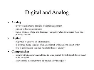
1.2 Digital and Analog source and system Key conception Digital information source produces a finite set of possible messages. Such as typewriter and keyboard Analog information source produces messages that are defined on continuum. Digital communication system transfers information from a digital source to the intended receiver(sink) Analog communication system transfers information from a analog source to the intended receiver(sink)
1.3 Deterministic and Random waveforms Deterministic waveform It can be modeled as a completely specified function of time Random waveform(stochastic waveform) It can not be completely specified as a function of time and must be modeled probabilistically Example:
1.4 The property of the book and methods of learning it 1)Property of the book a. from easiness to difficulty b. from concept to performance analysis 2) Methods of learning it a. reading it again and again b. grasping the important concept c. understanding the basic communication system by deriving some key formula d. simulation using Matlab
1.9 Information Measure 1. Information Content If the probabiltiy of transmitting jth message is Pj,the information content sent from a digital source when it was transmitted is given by:
From the definition, we have the following results: • The message that are less likely to occur provide more information • Information content depends on only the likehood of sending the message and does not depend on possible interpretation of the content as to whether or not it makes sense. 1.9 Information Measure
1) Bits,Nats and Hartley 1.9 Information Measure 2 Unit of information
1.9 Information Measure 2) Relationship between Bit,Nat and Hartley 2 Unit of information
3. Entropy for Digital Source 1.9 Information Measure Definition If there are m possible different source message in a digital source(m is finite), and Pj is the probabiltiy of sending the jth message, the entropy (also called average information) is:
1.9 Information Measure 4 Example1-1: In a string of 12 symbols, where each symbol consistis of one of four levels, there are 412 different combinations (words), since each levels is equally likely, and all the different words equally likely. Thus Pj=(1/4)12, And Ij=log2(1/(1/4)12)=12log2(4)=24bits
Source Rate is defined as Example: A1-2 A telephone touch-tone keypad has the digits 0 to 9 with probability of sending being 0.099 each, plus “*” and “#” with probability of sending being 0.005 each. If the keys are pressed at a rate of 2keys/s. compute the data rate for this source. 1.9 Information Measure Solution: 5 Source Rate Using define above, where T=1/2=0.5s/key, then:
1.10 Channel capacity For digital systems, the optimum system might be defined as the system that minimizes the BER at the system output subject to constraints on transmitted energy and channel bandwidth. Thus bit error rate and signal bandwidth are of prime importance in this course. Shannon gives channel capacity as
Where B is the channel bandwidth in hertz, S/N is the signal-to-noise power ratio at the input to the digital receiver. And showed that if the rate of information R(bits/s) was less than C,the BER would approach zero. 1.10 Channel capacity
1.10 Channel Capacity In analog system, the optimum system might be defined as the one that achieves the largest signal-to-noise ratio at the receiver output, subject to design constraints such as channel bandwidth and transmitted power. Nyquist showed that if a pulse represents one bit of data, noninterfering pulse could be sent over a channel no faster than 2B pulses/s, where B is the channel bandwidth in hertz. That is now known as the dimensionality theorem.
1.10 Channel Capacity Example SA1-3:A computer user plans to buy a higher-speed modem for sending data over his or her analog telephone line. The telephone line has a signal-to-noise ratio(SNR) of 25dB and passes audio frequencies over the range, from 300 to 3200Hz, Calculate the maximum data rate that could be sent over the telephone line when there are on errors at the receiving end. Solution: In the term of a power ratio, the SNR=10(25/10)=316.2, the bandwidth is B=3200-300= 2900 Hz,we get: Problem: Can a 28.8kbit/s modem work on this telephone line? And a 14.4kbits/s modem?
Homework Problems: 1.5, 1.7, 1.9,1.10, 1.12 ,1.13 1.15 Reading: page 1-2, §1-2 , §1-3, §1-6 §1-9, §1-10