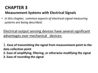
Measurement Systems with Electrical Signals in Engineering: AC and DC Fundamentals
400 likes | 541 Vues
Explore the fundamentals of measurement systems using electrical signals in engineering. Understand AC (Alternating Current) and DC (Direct Current) signals, their properties, and how transducers convert physical phenomena to electric signals. Dive into operational amplifiers, active filters, and the implications of loading errors. Learn to measure both AC and DC components accurately with DMMs (Digital Multimeters) and oscilloscopes, and grasp essential concepts like RMS (Root Mean Square) values, input/output resistances, and filter design. This comprehensive guide equips engineers with the foundational knowledge needed for accurate signal measurement and analysis.

Measurement Systems with Electrical Signals in Engineering: AC and DC Fundamentals
E N D
Presentation Transcript
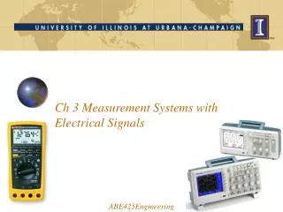
Ch 3 Measurement Systems with Electrical Signals ABE425Engineering
Agenda • AC and DC signals • Transducers • OpAmps • Active Filters • Loading error examples
AC and DC signals • Alternating Current (AC) • Direct Current (DC) • Most signals have both! • DC component (offset) measurement: Put DMM on DC • AC component measurement: Put DMM on AC • Scope gives Amplitude and peak-peak value • To get the scope trace at 0: Put input on gnd. • How is the scope amplitude related to the AC value on the DMM?
RMS value represents Power • DC: 12 Volt, R = 100 Ω • AC RMS value must give same power as DC of the same value • Mean value • Root Mean Square
Question • If an AC Voltmeter shows 12V RMS • What is the amplitude of this signal? • Simple AC Voltmeters measure the amplitude and divide by sqrt(2) • This only works for Sinusoidal signals!! • True RMS voltmeters measure real Power, Resistance and take the square root of the ratio • This works for ANY signal since it follows the definition of the power equalization of DC and AC signals • The RMS value is NOT the mean of the AC signal. It is the Root of the Mean of the Squared value!
Digital TRUE RMS meters digitize the signal and compute the RMS value from the definition • Digitize at least one cycle of the signal • Square it • Compute mean value • Integrate signal • Divide by cycle time • Take square root
A Transducer converts a physical measurand into an electric signal • Antenna • Cathode Ray Tube. LCD monitor • Fluorescent light, light bulb. • Light Emitting Diode (LEDs) • Magnetic stripe cards • Photocells/Light
Combined model of (a) input source, (b) amplifier and (c) output load • You want to prevent loading errors • Choose Ri high • Choose Ro low
Non-inverting OpAmp : Virtual ‘ground’ principle Since no current is flowing into the OpAmp: What is the input resistance for the source ?
f5_30 Inverting OpAmp
f5_30 Inverting OpAmp: Virtual ground principle Since no current is flowing into the OpAmp: What is the input resistance for the source ?
Capacitor equation Charge across Capacitor (Coulomb) Capacitance value (Fahrad (German for bicycle)) Voltage across Capacitor (Volt) Current through Capacitor (Ampere)
f5_31 Integrating Inverting OpAmp : Virtual ground
f5_31 Differentiating Inverting OpAmp: Virtual ground
A buffer gives an near infinite input resistance and a near zero output resistance • This method can be used to prevent a loading error • Virtual ground principle:
An instrumentation amplifier has twp high impedance (resistance) inputs • OpAmps have a very high input impedance (resistance) • This configuration has superb Common Mode Rejection Ratio (CMRR) up to 70 dB
A simple way to attenuate a signal is by using a voltage divider
Decibel notation • Addition is much simpler than multiplication • Notation in Bel (after Alexander Graham Bell) • For Power • For Voltages (Power ~ Voltage2) • In deciBel (0.1 Bel)
Common filters arrangements are low-pass, high-pass, band-pass and band-stop (notch)
Butterworth filters are smooth, but have a high roll-on roll-off factor.
Active filters combine amplification and filtering in one circuit! What is the input impedance the source ‘sees’?
Active Low-Pass filter analysis (1st order) Without C In general with impedances
Notation differences • Wheeler / Ganji • System • frequency in Hz • Corner frequency • Grift • System • frequency in rad/s • Corner frequency rad/s • Time constant (s)
Active High-Pass filter with OpAmp and Capacitor / Resistor pair (1st order) What is the input impedance the source ‘sees’?
Active High-Pass filter analysis Without C In general with impedances