IIR Filter Design Techniques for Digital Signal Processing
Learn about the different techniques used to design IIR filters for digital signal processing, including analog filter transformation and the bilinear transformation method.

IIR Filter Design Techniques for Digital Signal Processing
E N D
Presentation Transcript
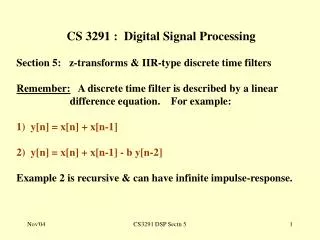
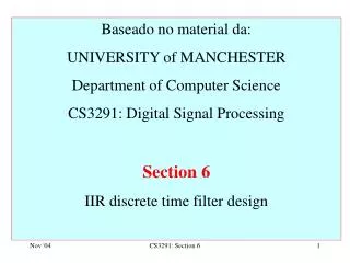
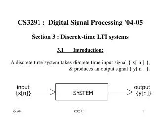
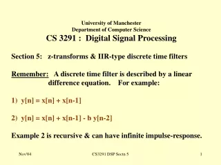
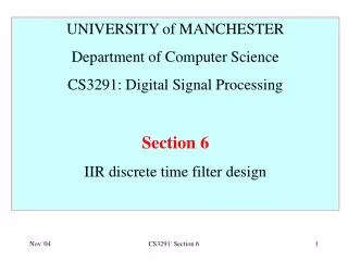
UNIVERSITY of MANCHESTER Department of Computer Science CS3291: Digital Signal Processing Section 6 IIR discrete time filter design CS3291: Section 6
6.1. Introduction: • Many design techniques for IIR discrete time filters have adopted ideas of analogue filters • Transform Ha(s) for analogue ‘prototype’ filter into H(z) for discrete time filter. • Begin with a reminder about analogue filters. 6.2. Analogue filters CS3291: Section 6
Analogue filters have transfer functions: • a0 + a1s + a2s2+ ... + aNsN • H a (s) = • b0 + b1s + b2s2 + ... + bMsM • Replace s by jw for frequency-response. • For RE(s) 0, Ha(s ) is Laplace Transform of h a (t). • In terms of poles and zeros: • (s - z 1 ) ( z - z 2 ) ... ( s - z N) • Ha(s) = K • (s - p 1 ) ( z - p 2 ) ... ( s - p M) • Many known techniques for deriving Ha(s); • e.g. Butterworth low-pass approximation • Analogue filters have infinite impulse-responses. CS3291: Section 6
Analogue Butterworth low-pass filter of order n [n/2] is integer part of n/2 & P = 0 /1 if n is even / odd CS3291: Section 6
Butterworth low-pass 1.2 1 0.8 Gain 0.6 n=1 0.4 n=2 n=4 0.2 0 0 1 2 3 4 5 6 radian/s CS3291: Section 6
x(t) 6.3 First order RC filter R y(t) C y(t) + RC dy(t)/dt = x(t) Take Laplace transforms: Y(s) + RC sY(s) = X(s) Y(s) 1 Ha(s) = = X(s) 1 + RC s 1 1 Ga (w) = Ha(j w) = = 1 + RC j w [ 1 + (w/wC ) 2 ] wC = 1/(RC) Shown graphically when wC = 1 CS3291: Section 6
Gain-response of RC filter CS3291: Section 6
Impulse response:- 0 : t < 0 ha (t) = (1/[RC]) e - t / (R C) : t 0 How to transform this filter to a discrete time filter? CS3291: Section 6
Example: A filter has system function H(s) = (1+s) / (1 + 2 s + 3 s2) . What is its differential equation. Solution: y(t) + 2dy(t)/dt + 3 d2y(t)/dt2 = x(t) + dx(t)/dt It’s easy! CS3291: Section 6
Transform an analogue filter with transfer functn H(s) into a digital filter. • Many ways exist. • We consider four. CS3291: Section 6
6.4. Firstly, dispose of a method that will not work. • Replacing s by z (or z -1 ) in Ha (s) to obtain H(z). • Taking previous example with RC = 1: • 1 1 • Ha (s) = H(z) = • 1 + s 1 + z • H(z) has pole at z = -1. • Even if we moved it to z=0.99, still no good:- CS3291: Section 6
With pole at z=-0.99, what does gain-response look like? G() High-pass instead of low pass. Forget this one. CS3291: Section 6
6.5 “Derivative approximation” technique • Differential equn of RC filter is: y(t) + RC dy(t)/dt = x(t) • Sample x(t), y(t) at T seconds to obtain x[n] & y[n]. • Assuming T small: Substituting : y[n] + RC ( y[n] - y[n-1] ) / T = x[n] (1 + RC/T) y[n] = x[n] + (RC/T) y[n-1] y[n] = a 0 x[n] - b 1 y[n-1] a 0 = 1/(1+RC/T) , b 1 = -RC / (T + RC) Recursive diffnce eqn. CS3291: Section 6
Signal flow graph for y[n] = a 0 x[n] - b1 y[n-1] CS3291: Section 6
For analogue filter : wC = 1/(RC) rad/s. • To make cut-off 500 Hz: RC = 1 / (2 x 500) = 0.0003183. • Let T = 0.0001 s , (fS =10 kHz.) • a 0 = 1/(1 + RC/T) = 0.239057 • b 1 = - RC/(T + RC) = - 0.760943 • Difference equation is: y[n] = 0.24 x[n] + 0.76 y[n-1] • 0.24 1 • H(z) = Ha(s) = • (1 - 0.76 z - 1 ) 1 + s/(5002) • 0.0576 1 • H(ejW)2 = H(jw)2 = • 1.58 - 1.52cos(W) 1 + (w / 3142)2 CS3291: Section 6
Compare gain-responses:- Shapes similar, but not exactly the same. Replaces s by (1 - z - 1 )/T Not commonly used CS3291: Section 6
6.6. “Impulse-response invariant” technique • Transforms analog prototype to IIR discrete time filter. • See text-books • Not on exam CS3291: Section 6
Intro to Bilinear Transformation method • Most common method for transforming Ha (s) to H(z) for IIR discrete time filter. • Consider derivative approximation technique: • D[n] = dy(t) /dt at t=nT ( y[n] - y[n-1]) / T. • dx(t) /dt at t=nT (x[n] - x[n-1]) / T. • d2y(t)/dt2 at t=nT (y[n] - 2y[n-1]+y[n-2])/T2 • d3y(t)/dt3 at t=nT (y[n]-3y[n-1]+3y[n-2]-y[n-3])/T3 • “Backward difference” approximation introduces delay which becomes greater for higher orders. • Try "forward differences" : D[n] [y[n+1] - y[n]] / T, etc. • But this does not make matters any better. CS3291: Section 6
Bilinear approximation: • 0.5( D[n] + D[n-1]) (y[n] - y[n-1]) / T • & similarly for dx(t)/dt at t=nT. • Similar formulae may be derived for d2y(t)/dt2, and so on. • If D(z) is z-transform of D[n] : • 0.5( D(z) + z-1D(z) ) = ( Y(z) - z-1Y(z) ) / T CS3291: Section 6
dy(t)/dt y(t) s If LT of y(t) is Y(s) LT of dy(t)/dt is sY(s). (2/T) (z-1)/(z+1) {dy(t)/dt / t=nT} {y[n]} replacing s by [ (2/T) (z-1)/(z+1)] is bilinear approximation. CS3291: Section 6
6.7. Bilinear transformation: • Most common transform from Ha (s) to H(z). • Replace s by (2 / T) (z-1) / (z+1) to obtain H(z). • For convenience take T=1. • Example • 1 1 • H a (s) = then H(z) = • 1 + RC s 1 + RC • z + 1 • = • (1 + 2RC)z + (1 - 2RC) CS3291: Section 6
Re-express as: 1 + z - 1 H(z) = K 1 + b 1 z - 1 where K = 1 / (1 + 2RC) & b 1 = (1 - 2RC) / (1 + 2RC) Properties: (z - 1) (i) H(z) = Ha(s) where s = 2 (z + 1) (ii) Order of H(z) = order of Ha(s) (iii) If Ha(s) is causal & stable, so is H(z). (iv) H(ejW) = Ha(j ) where = 2 tan(W/2) CS3291: Section 6
Proof of (iii): Let zp be a pole of H(z). • Then sp must be a pole of H a (s) where s p = 2 (z p - 1) / (z p + 1). • If s p = a + jb then (z p + 1)(a + jb) = 2 (z p - 1) , • a + 2 + jb (a + 2)2 + b2 • z p = and z p 2 = • -a + 2 - jb (2 - a)2 + b2 • Now a < 0 as H a (s) is causal & stable, z p must be < 1. • if all poles of H a (s) have real parts < 0, all poles of H(z) must lie inside unit circle. CS3291: Section 6
Proof of (iv): When z = ej, then ej- 1 2(e j / 2 - e - j / 2 ) s = 2 = ej + 1 e j / 2 + e -j / 2 2( 2 j sin ( / 2) = 2 cos ( / 2) = 2 j tan( / 2) CS3291: Section 6
Frequency warping: By (iv), H(ej) = Ha(j) with = 2 tan(/2). from - to mapped to in the range - to . CS3291: Section 6
Mapping approx linear for in the range -2 to 2. • As increases above 2 , a given increase in produces smaller and smaller increases in . CS3291: Section 6
Comparing (a) with (b) below, (b) becomes more and more compressed as . Frequency warping must be taken into account with this method CS3291: Section 6
6.8. Design of IIR low-pass filter by bilinear transfm Given cut-off frequency W C in radians/sample:- (i) Calculate w C = 2 tan(W C /2) radians/sec. (w C is "pre-warped" cut-off frequency) (ii) Find H a (s) for analogue low-pass filter with 1 radian/s cut-off. (iii) Scale cut-off frequency of Ha(s) to wC (iv) Replace s by 2(z - 1) / (z+1) to obtain H(z). (v) Rearrange the expression for H(z) (vi) Realise by biquadratic sections. CS3291: Section 6
ExampleDesign 2nd order Butterworth-type • IIR low-pass filter with W C = / 4. • Solution: Prewarped frequency w C = 2 tan( / 8) = 0.828 • Analogue Butterworth low-pass filter with c/o 1 radian/second: • 1 • H a (s) = • 1 + 2 s + s 2 • Scale c/o to 0.828, • 1 • H a (s) = • 1 + 2 s/0.828 + (s/0.828) 2 • then replace s by 2 (z+1) / (z-1) to obtain: • z 2 + 2z + 1 • H(z) = • z 2 - 9.7 z + 3.4 CS3291: Section 6
which may be realised by the signal flow graph:- CS3291: Section 6
6.9 Higher order IIR digital filters: • Normally cascaded biquad sections. • Example 6.3: Design 4th order Butterwth-type IIR low-pass digital filter with 3 dB c/o at fS / 16. . • Solution: (a) Relative cut-off frequency is /8. • Prewarped cut-off : C = 2 tan((/8)/2) 0.4 radians/s. • Formula for 1 radian/s cut-off is: Replace s by s/0.4 then replace s by 2 (z-1) / (z+1) to obtain: CS3291: Section 6
H(z) may be realised as: CS3291: Section 6
Compare gain-response of 4th order Butt low-pass transfer function used as a prototype, with that of derived digital filter. • Both are 1 at zero frequency. • Both are 0.707 at the cut-off frequency. • Analogue gain approaches 0 as w whereas digital filter gain becomes exactly zero at W = . • Shape of Butt gain response is "warped" by bilinear transfn. • For digital filter, cut-off rate becomes sharper as W because of the compression as w. CS3291: Section 6
6.10. High-pass band-pass and band-stop IIR filters • Apply bilinear transformation to Ha(s) obtained by frequency band transformations. • Cut-off frequencies pre-warped to find analog c/o frequencies. • Example: 4th order band-pass filter with W L = /4 , W u = /2. • Solution: Pre-warp both cutoff frequencies: • w L = 2 tan ((/4)/2) = 2 tan(/8) = 0.828 , • u = 2 tan((/2)/2)) = 2 tan(/4) = 2 • Need 4th order H a (s) with pass-band L to U . • Start from 2nd order Butt 1 radian/sec: • H a (s) = 1 / (s 2 + 2 s + 1). • Replace s by (s 2 + 1.66 ) / 1.17 s to obtain: • 1.37 s 2 • Ha(s) = • s 4 + 1.65 s 3 + 4.69 s 2 + 2.75 s + 2.76 CS3291: Section 6
We have a problem as the denominatr is not product of 2nd order expressions in s. • We have to re-express it in this form. • This cannot be done without a computer! • One way is to find the roots of the denom using MATLAB: • roots([1 1.64 4.69 2.75 2.76]) • -0.54 + 1.7 j -0.54 - 1.7 j • -0.28 + 0.88 j -0.28 - 0.88 j • (s - ( -0.54 +1.7j ) ) (s - (-.54-1.7j ) ) = ( s2 + 1.08s + 3.18) • (s - (-0.28 + 0.88 j) ) ( s - (-0.28 - 0.88) ) = (s2 + 0.56s + 0.85) CS3291: Section 6
After factorising (using MATLAB): • 1.37 s 2 • H a (s) = • (s 2 + 1.08 s +3.18)(s 2 +0.56 s + 0.85) • Replace s by 2(z - 1)/(z + 1):- • 5.48 (z - 1) 2 (z + 1) 2 • H(z) = • (9.4 z 2 - 1.57 z + 5 ) ( 6 z 2 - 6.3 z + 3.7) CS3291: Section 6
Rearrange into 2 biquad sections: 1 - 2 z -1 + z - 2 1 + 2 z - 1 + z - 2 H(z) = 0.1 1 - 0.17 z -1 + 0.54 z -2 1 - 1.05 z -1 + 0.62 z-2 whose gain response is: CS3291: Section 6
There are alternative ways of converting Ha(s) into second order sections (SOS) in the MATLAB SP tool-box. • Can replace s by 2(z - 1)/(z + 1) in the ‘4th order sectn’ expression for Ha(s) then use • [sos G] = tf2sos ([a4 a3 a2 a1 a0], [b4 … b0 ]) • tf2sos does not like functions of s. • So we have to convert to a digital filter before using it. • ‘help tf2sos’ to find out abt this function • I will try to find a more elegant way of doing this one day! CS3291: Section 6
Option of cascading high pass & low-pass digital filters to give band-pass or band-stop filters must be used with care. • It is much simpler & avoids the factorisation problem. • Calculate U & L by prewarping U & L • Then make sure that analogue prototype is wide-band i.e. U >> 2 L before applying bilinear transformatn. • If it’s not wide-band, use the factorisation method. • High-pass filters are easy: • Apply transformation s C/s to Ha(s) for a 1 radian/s low-pass filter where C is prewarped c/o freq. • Then apply the bilinear transformation as usual. CS3291: Section 6
Final note: All these design techniques, and many more, are available in the MATLAB SP toolbox. End of ‘bilinear transformation’ method CS3291: Section 6
6.11. Comparison of IIR and FIR digital filters: Advantage of IIR type digital filters: Economical in use of delays, multipliers and adders. Disadvantages: (1)Sensitive to coefficient round-off inaccuracies & effects of overflow in fixed point arith. These effects can lead to instability or serious distortion. (2) An IIR filter cannot be exactly linear phase. CS3291: Section 6
Advantages of FIR filters: (1) may be realised by non-recursive structures which are simpler and more convenient for programming especially on devices specifically designed for DSP. (2) FIR structures are always stable. (3) Because there is no recursion, round-off and overflow errors are easily controlled. (4) An FIR filter can be exactly linear phase. Disadvantage of FIR filters: Large orders can be required to perform fairly simple filtering tasks. CS3291: Section 6
Problems: 1 Find H(s) for 3rd order Butterwth low-pass filter with C = 1. 2. Find H(s) for 3nd order Butterworth low-pass analog filter with cut-off C Give its differential equation. Apply derivative approx technique to derive 3rd order IIR Butterwth-type digital filter with cut-off 500 Hz where fS= 10 kHz. 3. A 3rd order low-pass IIR discrete time filter is required with 3 dB cut-off at f S /4. Apply bilinear transfn to Butterwth low- pass transfer function to design it & give its signal flow graph as 2nd & 1st order sections in serial cascade. 4. Give program to implement 3rd order IIR filter above in floating point arithmetic. Then do it in fixed point arithmetic. 5. Low-pass IIR digital filter required with cut-off at f s / 4 & stop-band attenuation at least 20 dB for all frequencies above 3f s /8 & below f s /2. Design by bilinear transfn applied to H(s) for Butterwth low-pass, showing that minimum order required is 3. CS3291: Section 6
6 Butterworth-type IIR low-pass digital filter needed with 3 dB c/o at fS / 16. Attenuation must be at least 24 dB above fS / 8. What order is needed? Solution: (a) Relative cut-off frequency is /8. Prewarped cut-off : C = 2 tan((/8)/2) 0.40 radians/s. For n t h order Butt low-pass filter with cutoff C , gain is: 1 H a (j) = [1 + (/0.4) 2 n ] Gain of IIR filter must be < -24dB at = /4. H a (j) must be < -24 dB at = 2 tan((/4)/2) 0.83 20 log 1 0(1/[1+(.83/.4) 2 n ]) < -24 i.e. [1 + (2.1) 2 n ] >10 1.2 Hence 1 + (2.1) 2 n > 10 2 . 4 = 252 . 2.1 2n > 251 n = 4 is smallest possible CS3291: Section 6
7. Design a 4th order band-pass IIR digital filter with lower & upper cut-off frequencies at 300 Hz & 3400 Hz when fS = 8 kHz. 8. Design a 4th order band-pass IIR digital filter with lower & upper cut-off frequencies at 2000 Hz & 3000 Hz when fS = 8 kHz 9. (This is really for Sectn 5) . What limits how good a notch filter we can implement on a fixed point DSP processor? In theory we can make notch sharper & sharper by moving poles closer & closer to zeros. What limits us in practice. I wonder how sharp a notch we could get in 16-bit fixed pt arithmetic? CS3291: Section 6