Remote Controlled Robot Arm: PCB Design and Layout Overview
90 likes | 172 Vues
Explore the detailed PCB design and layout considerations for a 6-degree-of-freedom remote-controlled robot arm project. Learn about the power supply, communication modules, and digital circuits involved. Layouts for control sleeve, robot arm, and microcontroller PCBs are discussed.

Remote Controlled Robot Arm: PCB Design and Layout Overview
E N D
Presentation Transcript
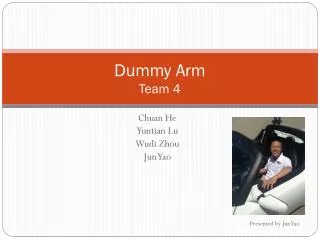
Dummy ArmTeam 4 Presented by Yuntian Lu
Project Overview • An remote controlled robot arm with 6 degree of freedom. It consists of two major component control sleeve and robot arm. Control sleeve is responsible for measuring the motion of the human arm. Robot arm will mimic the same motion.
Overall PCB design consideration • Separate components into three modules: • Power Supply • Communication modules(XBee) • Digital circuit(microcontroller)
Microcontroller PCB layout consideration • Decoupling capacitor • Level convertor Control Sleeve MCU Robot Arm MCU
Power Supply PCB layout consideration • Wider trace for GND and VCC • Heat dissipation on linear regulator Control Sleeve Power Supply Robot Arm Power Supply