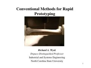
Conventional Methods for Rapid Prototyping
Conventional Methods for Rapid Prototyping. Richard A. Wysk Dopaco Distinguished Professor Industrial and Systems Engineering North Carolina State University . Agenda. Why is Rapid Manufacturing (RM) important in medicne ? What is RM/RP? Limitations of RP Economics of RM/RP

Conventional Methods for Rapid Prototyping
E N D
Presentation Transcript
Conventional Methods for Rapid Prototyping Richard A. Wysk Dopaco Distinguished Professor Industrial and Systems Engineering North Carolina State University
Agenda • Why is Rapid Manufacturing (RM) important in medicne? • What is RM/RP? • Limitations of RP • Economics of RM/RP • New directions in RM • Sustainable RM • Observations and conclusions
Broad focus -- Engineering integration ENGINEERING -- the planning, designing, construction (manufacture), or management of machinery, roads, bridges, etc..
A Vision of Integrated Engineering Systems (cont.) INTEGRATE • 1. to make or become whole or complete. • 2. to bring parts together as a whole. • 3. to remove barriers imposing segregation.
A Vision of Integrated Engineering Systems (cont.) INTEGRATED ENGINEERING • planning, designing, construction and management of a product.
Function, Cost, weight User, etc. Specification PRODUCT ENGINEERING Performance PLANNING DESIGN CONTROL Assemblies PRODUCTION ENGINEERING Parts Manufacturability Raw Materials Capabilities PROCESS ENGINEERING Engineering Integration
A Vision of Integrated Engineering Systems (cont.) INTEGRATION ENGINEERING • tools and techniques that can be used to assist in combining planning, design, construction and management of a product.
A Vision of Integrated Engineering Systems (cont.) • INTEGRATED ENGINEERING • planning, designing, construction and management of a product.
Engineering Integration • Performing all business activities in unison • Analyzing all engineering functions concurrently • Making wise real-time economic decisions • Team concepts
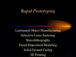
Need for model accuracy increases What does this have to do with Rapid Prototyping (RP) • Prototyping is critically important during product/process design • Reduce time to market • Early detection of errors • Assist concurrent manufacturing engineering • Prototypes are used to convey a products’: • Form • Fit • Function • Prototype building can be a time-consuming process requiring a highly skilled craftsperson • Time spent testing prototypes is valuable • Time spent constructing them is not… • “Rapid Prototyping” (RP) methods have emerged • (Solid Freeform Fabrication, Additive Manufacturing, Layered Manufacturing)
Rapid Manufacturing definitions • Rapid Manufacturing (RM) • Direct from CAD model without tooling • No process engineering • Short lead time • Increased product fidelity • Ready to use end products • Additive processes • Traditional Rapid prototyping (RP) process • 3D printer, SLA, FDM, SLS… • No geometry limitation • Push button manner operation • Restricted in material, accuracy, and surface finish Image from http://www.tctmagazine.com/x/guideArchiveArticle.html?id=10839
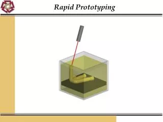
Stereolithography (SLA) Stereolithography is a common rapid manufacturing and rapid prototyping technology for producing parts with high accuracy and good surface finish. A device that performs stereolithography is called an SLA or Stereolithography Apparatus. Stereolithography is an additive fabrication process utilizing a vat of liquid UV-curablephotopolymer "resin" and a UVlaser to build parts a layer at a time. On each layer, the laser beam traces a part cross-section pattern on the surface of the liquid resin.
Selective Laser Sintering (SLS) SLS can produce parts from a relatively wide range of commercially available powder materials, including polymers (nylon, also glass-filled or with other fillers, and polystyrene), metals (steel, titanium, alloy mixtures, and composites) and green sand. The physical process can be full melting, partial melting, or liquid-phase sintering. And, depending on the material, up to 100% density can be achieved with material properties comparable to those from conventional manufacturing methods. In many cases large numbers of parts can be packed within the powder bed, allowing very high productivity.
Fused Deposition Modeling (FDM) • Fused deposition modeling, which is often referred to by its initials FDM, is a type of rapid prototyping or rapid manufacturing (RP) technology commonly used within engineering design. The FDM technology is marketed commercially by Stratasys Inc. • Like most other RP processes (such as 3D Printing and stereolithography) FDM works on an "additive" principle by laying down material in layers. A plastic filament or metal wire is unwound from a coil and supplies material to an extrusion nozzle which can turn on and off the flow. The nozzle is heated to melt the material and can be moved in both horizontal and vertical directions by a numerically controlled mechanism, directly controlled by a Computer Aided Design software package. In a similar manner to stereolithography, the model is built up from layers as the material hardens immediately after extrusion from the nozzle. • Several materials are available with different trade-offs between strength and temperature. As well as Acrylonitrile butadiene styrene (ABS) polymer, the FDM technology can also be used with polycarbonates, polycaprolactone, and waxes. A "water-soluble" material can be used for making temporary supports while manufacturing is in progress. Marketed under the name WaterWorks by Stratasys this soluble support material is actually dissolved in a heated sodium hydroxide solution with the assistance of ultrasonic agitation.
Laminated Object Manufacturing (LOM) Laminated Object Manufacturing (LOM) is a rapid prototyping system developed by Helisys Inc. (Cubic Technologies is now the successor organization of Helisys) In it, layers of adhesive-coated paper, plastic, or metal laminates are successively glued together and cut to shape with a knife or laser cutter.
Electron Beam Melting (EBM) • Electron Beam Melting (EBM) is a type of rapid prototyping for metal parts. The technology manufactures parts by melting metal powder layer per layer with an electron beam in a high vacuum. Unlike some metal sintering techniques, the parts are fully solid, void-free, and extremely strong. Electron Beam Melting is also referred to as Electron Beam Machining. • High speed electrons .5-.8 times the speed of light are bombarded on the surface of the work material generating enough heat to melt the surface of the part and cause the material to locally vaporize. EBM does require a vacuum, meaning that the workpiece is limited in size to the vacuum used. The surface finish on the part is much better than that of other manufacturing processes. EBM can be used on metals, non-metals, ceramics, and composites.
So what’s the problem? physical models • Rapid Prototyping? • Technology for producing accurate parts directly from CAD models in a few hours with little need for human intervention. • Pham, et al, 1997 • Prototype? • A first full-scale and usually functional form of a new type or design of a construction (as an airplane) • Webster’s, 1998 • Model? • A representation in relief or 3 dimensions in plaster, papier-mache, wood, plastic, or other material of a surface or solid • Webster’s, 1986 How can we automatically create toolpath and fixture plans for CNC?
Problems with Additive RP • Long processing times • Energy use • Expensive product ?!? • Not intended as a production technique • Functional product ?!? • May not quite meet material or dimensional requirements
CNC Machining Computer numerical control, and refers specifically to a computer "controller" that reads G-code instructions and drives a machine tool, a powered mechanical device typically used to fabricate components by the selective removal of material. CNC does numerically directed interpolation of a cutting tool in the work envelope of a machine. The operating parameters of the CNC can be altered via a software load program.
Economics This is the cost for all parts that will be made and sold. This is the cost for each part that will be made and sold. Product cost = engineering cost + materials cost + manufacturing cost Product cost /part = engineering cost / total # of parts + materials cost / part + manufacturing cost / part
Engineering cost • Product design (Ced) • Cost of engineering design • Process design (Cpc) • Cost of process planning • How is the part to be made • Cost of fixtures and tooling • Production design (Cpd) • Cost of setting up production 26
Material cost • In most cases this is somewhat dependent of the number of parts • Economies of scale • Efficiencies of scale • Additive or subtractive • Fractional or bulk materials 27
Engineering cost CE = Ced / nt + Cpc / nt + Cpd / nb total parts total parts parts in a batch 28
Manufacturing cost • One time costs • Process planning and design • Fixture engineering and fabrication • Set up cost (Cset) • Cost to set up a process • Processing cost (Cpsc) • Cost of processing a part • Production cost (Cpdc) • Cost of tooling and perishables 29
Manufacturing cost CM = Cone / nt +Cset / nb + Cpsc + Cpdc/ ntool Total partsparts in a batch each part tool cost by parts/tool 30
Economic Analysis Subtractive Process Additive Process A general cost model Tooling, Planning, Design
So how can engineering costs be reduced for CNC machining? Machine cost Fixture cost Process planning cost
CNC-RP Method: A part is machined on a 3-Axis mill with a rotary indexer and tailstock using layer-based toolpaths from numerous orientations about an axis of rotation.
Process/fixture planning time: Minutes Processing time ~20 hours Material: Steel Layer depth: 0.001” (0.025mm)
Setups/Orientation Planning VISIBILITY MACHINABILITY (for a given tool geometry)
Toolpath layers at 0º orientation Toolpath layers at 180º orientation z y x z y x z z y y Methodology • Overview: • Visible surfaces of the part are machined from each orientation about an axis of rotation • Long, small diameter flat end tool with equal flute and shank diameter used. • Sacrificial supports (temporary features) added to the solid model and created in-process • Begin with round stock material, clamped between two opposing chucks • Example:
Research Problems • Setup/Orientation • How many rotations (setup orientations) about the axis of rotation are required? • Where are they? • Toolpath planning • For each orientation, how can we automatically generate toolpaths? • What diameter and length tools should be used? • In what order should the toolpaths be executed? • Fixture planning • How can we automatically generate sacrificial supports? • What diameter and length should they be?
Rapid Prototyping • Basics: • Solid model (CAD) is converted to STL format • Facetted representation where surface is approximated by triangles • Intersect the STL model with parallel planes to create cross sections • Create each cross section, adding on top of preceding one CAD (ProE) STL “slicing” operation 2-D cross section
Model material Support material Build Platform Rapid Prototyping • Fixtures are created in-process (Sacrificial Supports) • Secure model to the build platform • Support overhanging features • Remove fixture materials in post-process step FDM Model with/without supports
Determining the number of rotations • A problem of tool accessibility • Approximated as a problem of visibility (line of sight) • A Visibility map is generated via a layer-based approach • Tool access is restricted to directions in the slice plane (2D problem) • Goal is to generate the data necessary to determine a minimum set of rotations required to machine the entire surface Set of segments on a slice visible from one tool access direction
Approaches to 2D visibility mapping • Shortest Euclidean paths - Lee and Preparata, 1984 • Convex ropes - Peshkin and Sanderson, 1986 • 2D visibility cones - Stewart, 1999 • Issues: • Computing S.E.P.s/VCs for polygons with holes • Granularity of STL files, may need to add collinear points to polygon segments • Would need to retriangulate
Solution approach • Visibility for each polygonal chain is determined by calculating the polar angle range that each segment of the chain can be seen. • Since there can be multiple chains on each slice, we must consider the visibility blocked by all other chains. (b) Visibility for the segment= [Θa,Θb,], [Θc,Θd,] (a) Visibility for the segment= [Θa,Θb,]
Pi+1 not visible Pi-1 Pi+1 P: , S: LCHP RCHP Pi RCHP LCHP Pi Step one: Visibility with respect to own chain • We have a polygon P and its convex hull S • For any point Pinot on S, the visible range can be found by investigating points from the adjacent CCW convex hull point to the adjacent CW convex hull point • These points will be denoted the “left” and “right” convex hull points of Pi, LCHP(Pi) and RCHP(Pi), respectively. • It is only necessary to calculate the polar angles from Pi to the points in the set [LCHP, RCHP], excluding Pi. • The set is divided into, S1 and S2 where:
V(Pi): [43.82 ,121.31] S1 S2 V(Pi) Pi • The visible range for a point is bounded by the minimum polar angle from Pi to points in S1 and the maximum polar angle from Pi to points in S2. • This is the visible range for the point Piwith respect to the boundary of its own chain, and is denoted V(Pi). • Where:
RVv LVv LVu RVu u-1 v+1 v u • Consider the segment defined by points in P, u and v, where: • u: Pi and v: Pi+1 • The intersection of visibility ranges for the points u and v and the 180º range above the segment define a feasible range of polar angles in which the segment could be reached. • The sets S1 and S2 are redefined: • The ends of the visibility range are:
LV I1 u I2 v I2 u v I1 LV RV (a) (b) RV RV LV RV LV I2 I2 I1 I1 v u u v (c) (d) Problem Surfaces (a) RV is outside of the 180º range, (b) Both RV and LV are out of the 180º range, (c) No visibility due to overlapping, (d) Visibility to the entire segment is not possible since RV > LV.
Step two: Visibility blocked by all other chains on the slice • V( )j* is the visibility with respect to the chain j on which resides, denoted j*. • For all obstacle chains , the polar range blocked by the chain is denoted VB( )j. • The set of visible ranges for the segment is defined: • Visibility blocked to the segment is the union of the visibility blocked by chain j to point u and the visibility blocked by chain j to point v, intersected with the 180º range above segment • The set of angles blocked to the segment where: • The set of angles blocked to points u and v where:
LBu RBv LBv RBu v u • Considering the condition that blocked visibility is only for blockage in the 180º range above the segment, it can easily be seen that the set: • RBu is simply the minimum polar angle from u to all points on the blocker chain • LBv is the maximum polar angle from v to all points on Pj, where Pj is the set of points for the blocker chain.