Download
1 / 38
410 likes | 646 Vues
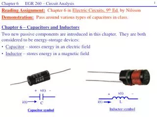
Chapter 6 EGR 260 – Circuit Analysis. 1. Reading Assignment: Chapter 6 in Electric Circuits, 9 th Ed. by Nilsson Demonstration: Pass around various types of capacitors in class. Chapter 6 – Capacitors and Inductors

E N D
Chapter 6 EGR 260 – Circuit Analysis 1 Reading Assignment:Chapter 6 in Electric Circuits, 9th Ed. by Nilsson Demonstration:Pass around various types of capacitors in class. • Chapter 6 – Capacitors and Inductors • Two new passive components are introduced in this chapter. They are both considered to be energy-storage devices: • Capacitor – stores energy in an electric field • Inductor – stores energy in a magnetic field Capacitor symbol
Chapter 6 EGR 260 – Circuit Analysis 2 Electrons are attracted to the positive terminal of the source leaving a depletion of electrons and a positively charged plate. Charge = +Q - - - + + + + + + + + + + + + + + + + + + + + + + + Total Charge = (+Q) + (-Q) = 0 _ _ _ _ _ _ _ _ _ _ _ _ _ _ _ _ _ _ _ _ _ _ Electrons are repelled by the negative terminal of the source leaving an abundance of electrons and a negatively charged plate. Charge = -Q - - - Capacitors The simplest type of capacitor is a parallel plate capacitor. Consider the result of placing a voltage across two parallel plates as shown below.
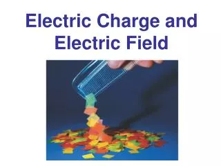
Chapter 6 EGR 260 – Circuit Analysis 3 Electric flux lines + + + + + + + + + + E - - - - - - - - - - Electric field As discussed in Chapter 1, a force is exerted between oppositely charged particles (it can be calculated using Coulomb’s Law). When charged is distributed over a surface (such as with the plates of a capacitor), this force is represented by an electric field, E. The electric field is measured as force per unit charge, or E = F/Q. The electric field is represented by electric flux lines. Recall that a capacitor is an energy storage device – it stores energy in an electric field. Electric fields are studied in depth in a course in electromagnetism. An electric field, E, exists between the charged plates of a capacitor Charge and capacitance The charge on each plate is proportional to the voltage across the plates, so Q V or more specifically Q = CV where C = capacitance Typical values:The Farad is a large unit. Most capacitors have capacitance values in the F, nF, or pF range; although some capacitors in the F range are available (generally at low voltages).
Chapter 6 EGR 260 – Circuit Analysis 4 Capacitor current Recall that current for any device can be found using the relationship: so capacitor current is found as follows: Key relationship:This is sort of like Ohm’s Law for a capacitor. Capacitance symbol The capacitor is a passive device so the relationship above depends on the use of passive sign convention. The general symbol for a capacitor is shown below. Note that the symbol looks like two parallel plates.
Chapter 6 EGR 260 – Circuit Analysis 5 Physical Characteristics Capacitance can also be determined from the physical dimensions of the capacitor using A = Area of plate (in m2) where , A, and d are illustrated in the figures shown. d = distance between plates (in m) Dielectric = material between the plates and = permittivity of the dielectric (in F/m) d
Chapter 6 EGR 260 – Circuit Analysis 6 The permittivity of a given material is often expressed in terms of how it relates to the permittivity of a vacuum using: = Ro where o = permittivity of a vacuum = 8.85 x 10⁻¹² F/m R = relative permittivity (a few examples are shown below) Note: 1 mil = 0.001” Dielectric strength is a measure of how much voltage would be required to jump across a gap, similar to how a spark jumps across the gap on a spark plug. Note that if a spark plug uses a gap of 0.032”, a voltage of = (32 mil)(75V/mil) = 2400V is necessary to create a spark. A dielectric for a capacitor is chosen to insure that the voltage will not arc across the capacitor. So the voltage rating for a capacitor is related to the dielectric strength and the gap size (which affects the value of C).
Chapter 6 EGR 260 – Circuit Analysis 7 Example: Calculate the value of C for a teflon capacitor with rectangular plates that measure 2 cm by 4 cm, and a distance of 0.1 mm between the plates. Also calculate the maximum voltage rating for the capacitor.
Chapter 6 EGR 260 – Circuit Analysis 8 Variable Capacitors Recall that so how can C be varied? 1) by varying d, the distance between the plates 2) by varying A, the area between the plates (actually by rotating one plate to change the amount of overlap between plates). Method 2: Varying A Turning the screw changes the amount of overlap between the plates. Note: Using multiple plates acts like capacitors in parallel which add together (to be proven shortly) Method 1: Varying d Tightening the screw reduces the distance between the plates and increases C. Reference: Intro. Circuit Analysis, 6th Ed., by Boylestad Top view 50% overlap No overlap 100% overlap Reference: All Electonics (www.allelectronics.com Bottom view
Chapter 6 EGR 260 – Circuit Analysis 9 Two categories of capacitors Capacitors are sometimes separated into two categories: 1) Polarized (electrolytic) 2) Non-polarized (non-electrolytic) • Electrolytic capacitors • have polarity markings and may be damaged (or even explode) if used with reverse polarity • are often cylindrical shaped (appear like a metal can) • are constructed using a large roll of aluminum foil coated with Al·O2 where the aluminum acts as the positive plate and the oxide as the dielectric. A layer of paper is placed over oxide coating and then another roll of aluminum foil without the oxide coating is added to act as the negative plate. This results in a very large plate area, A, and a very small distance, d, between the plates (the thickness of the oxide coating). • most large capacitors (F range) are electrolytic Non-electrolytic capacitors Most small capacitors (nF and pF range) are non-electrolytic
Chapter 6 EGR 260 – Circuit Analysis 10 Capacitor symbols - A special symbol is often used with electrolytic capacitors to designate the negative terminal as shown below. Electrolytic capacitors - images showing internal construction Reference: Oak Ridge National Labs (www.ornl.com) Image 1: External view of an electrolytic capacitor Image 3: Tomographic image of the capacitor showing the roll of foil inside.ctrolytic capacitor showing the roll of aluminum foil (reference: Oak Ridge National Labs (www.ornl.com) Image 2: Digital radiograph of the capacitor showing the roll of foil inside.
Chapter 6 EGR 260 – Circuit Analysis 11 Various types of capacitors(reference: All Electronics (www.allelectronics.com) Mylar Capacitor (0.22F, 100V) Axial Electrolytic Capacitor (47F, 25V) Metalized Polyester Capacitor (2F, 200V) Ceramic Disc Capacitor (0.22F, 1000V) Monolithic Ceramic Capacitor (22nF) Radial Electrolytic Capacitor (47F, 25V) Snap In Capacitor (330F, 400V) Super Capacitor (1F, 2.5V) DIP Capacitor (2.2nF, 50V) Photo Flash Capacitor (150F, 300V)
Chapter 6 EGR 260 – Circuit Analysis 12 Key capacitor relationships: Show that
Chapter 6 EGR 260 – Circuit Analysis 13 Example: Find i(t) through the capacitor shown if v(t) = 6e-2t V. Example: Find v(t) across the capacitor shown if i(t) = 10cos(400t) mA. Example: Calculate the maximum energy that could be stored in two of the capacitors that were passed around in class.
Chapter 6 EGR 260 – Circuit Analysis 14 Example: Sketch i(t), p(t), and w(t) if the graph of v(t) shown below represents the voltage across a 100 F capacitor.
Chapter 6 EGR 260 – Circuit Analysis 15 Series Capacitance Use KVL to show that (Series capacitors combine like parallel resistors)
Chapter 6 EGR 260 – Circuit Analysis 16 Parallel Capacitance Use KCL to show that (Parallel capacitors combine like series resistors) Example: Find the equivalent capacitance between terminals a and b.
Chapter 6 EGR 260 – Circuit Analysis 17 Leakage Resistance If an ideal capacitor is “charged” to a certain voltage and is then open-circuited, it should maintain its voltage (and stored energy) forever. Actual capacitors will lose their voltage over time (some in a few seconds and others may take several hours). This is due to a very small leakage current which flows through the dielectric. This effect is modeled by adding a leakage resistance in parallel with the capacitor as shown below. Typical Values of Leakage Resistance Ceramic capacitor - 1000 M Mica capacitor - 1000 M Polyester-film capacitor - 100 M Electrolytic capacitor - 1 M
Chapter 6 EGR 260 – Circuit Analysis 18 Stray Capacitance We have seen that a capacitor can be formed using two parallel plates. This essentially means that any two surfaces could potentially act like a capacitor. This type of capacitance is referred to as stray capacitance. Stray capacitance is usually very small (less than a few pF), but can cause serious problems at high frequency. For this reason, many high frequency circuits use shielded cables and components. Examples: Illustrate stray capacitance between: a) two wires b) the junctions in an npn BJT (transistor)
Chapter 6 EGR 260 – Circuit Analysis 19 • Two key facts about capacitors: • 1) A capacitor’s voltage cannot change instantaneously. • This is sometimes expressed as VC(0+) = VC(0-) • Discussion: • 2) A capacitor looks like an open-circuit in steady-state. • “Steady-state” means that there have been no recent changes in the circuit or that any changing voltages or currents have had time to reach their final values. • Discussion:
Chapter 6 EGR 260 – Circuit Analysis 20 t = 0 Example: In the circuit shown below the capacitors are initially uncharged. The switch closes at t = 0 and after a “long time” the circuit reaches steady-state. Find the voltage across each capacitor after the circuit reaches steady-state.
Chapter 6 EGR 260 – Circuit Analysis 21 Example: The switch had been closed for a long time before it was opened at t = 0.
Chapter 6 EGR 260 – Circuit Analysis 22 windings (N = 5.5 turns in this diagram) magnetic flux, f magnetic field lines core f + v(t) - i(t) A voltage, v(t) is “induced” across the windings A current, i(t) is passed through the windings Inductors An inductor is a passive device created by wrapping wire around a core. When time-varying current passes through the coil a magnetic field is created and a voltage is “induced” across the coil. Inductors are also called “chokes” or “coils”.
Chapter 6 EGR 260 – Circuit Analysis 23 Magnetic flux In the previous diagram it was shown that a magnetic flux, , flowed through the core. Magnetic flux is measured in units of Webers, Wb. It is somewhat like a magnetic current flowing through the core. The direction of the magnetic flux is determined using the “right-hand rule”. Right-hand rule: Using your right hand, curl your fingers in the direction that the current flows through the coil and your thumb will indicate the direction of the magnetic flux. Example: Sketch inductors with various types of cores and show the magnetic flux.
Chapter 6 EGR 260 – Circuit Analysis 24 Inductance N = number of windings around the core = flux linkage = N is also proportional to the current or = (constant)i This constant is referred to as inductance, L Note: More detailed information on magnetic fields is covered in a later course in electromagnetics. = N = Li The voltage induced across the coil is equal to the derivative of the flux linkage, so So a key relationship for inductors is: Notes: 1) This equation is sort of like “Ohm’s Law” for an inductor. 2) Be sure to use passive sign convention 3) Note that the inductor symbol looks like a coil of wire.
Chapter 6 EGR 260 – Circuit Analysis 25 lC = length of core (in m) A = cross-sectional area of the core (in m2) N = number of turns (complete 360 wraps) Physical Characteristics The value of L can also be determined from the physical properties of the inductor using Where N = number of turns A = cross-sectional area of the core (in m2) lc = length of the core (in m) = permeability of the core
Chapter 6 EGR 260 – Circuit Analysis 26 Permeability of the core Permeability can be thought of as a measure of how well a type of material can sustain a magnetic field. = permeability of the core. This is typically expressed as: = Ro • where o = 4 x 10⁻⁷ Wb/Am and R = relative permeability • There are only basically two values for R : • R = 1 for non-ferrous materials • R 200 for ferrous materials • The equation for inductance can now be written as: So the value of L is increased by a factor of 200 simply by using an iron core!
Chapter 6 EGR 260 – Circuit Analysis 27 Typical values Inductors are sometimes classified in two broad categories: 1) iron-core inductors - typical values in the H range 2) non-iron core inductors - typical values in the H or mH range Demonstration - Pass around various types of inductors in class. Example - Calculate the approximate value of L for one of the inductors in class by estimating the dimensions and the number of turns.
Chapter 6 EGR 260 – Circuit Analysis 28 Examples of inductors (www.allelectronics.com) 3.5mH bobbin choke Variable choke with adjustable ferrite 220uH drum choke 346uH inductor (toroid) 390uH choke coil 4mH high-current choke
Chapter 6 EGR 260 – Circuit Analysis 29 Examples of inductors (www.ctparts.com) Air-core inductor Peaking coils Power inductor Toroidal power chokes (www.coilcraft.com) Power line choke Wire-wound inductors
Chapter 6 EGR 260 – Circuit Analysis 30 Key inductor relationships: Show that
Chapter 6 EGR 260 – Circuit Analysis 31 Example: Find i(t) through the inductor shown if v(t) = 2e-40t V. Assume that there is no initial energy stored in the inductor. Example: Find v(t) across the inductor if i(t) = 10cos(400t) mA. Example: The toroidal inductor shown has L = 46 mH and is rated for a maximum current of 2A. What is the maximum energy that could be stored in the inductor?
Chapter 6 EGR 260 – Circuit Analysis 32 Example: Sketch v(t), p(t), and w(t) if the graph of i(t) shown below represents the current through a 2H inductor.
Chapter 6 EGR 260 – Circuit Analysis 33 Series Inductance KVL can be used to show that: (Series inductors combine like series resistors) Parallel Inductance KCL can be used to show that: (Parallel inductors combine like parallel resistors) Example: Find the equivalent inductance between terminals a and b.
Chapter 6 EGR 260 – Circuit Analysis 34 • Non-ideal effects in inductors • Resistors and capacitors typically act quite closely to their ideal models. Inductors, however, often do not. There are numerous non-ideal effects in inductors, including: • coil resistance • eddy currents • hysteresis • L varies somewhat with current (it should be a constant) • L varies somewhat with frequency (it should be constant) • Additionally, inductors are often bulky compared to capacitors. In some cases, circuits with capacitors or inductors can be used to perform the same function. In these cases, capacitor circuits are preferred due to the problems with inductors listed above. • Inductor models often include a series coil resistance, as shown below. Typical values of Rcoil: From a few ohms (small inductors) to hundreds of ohms (large iron-core inductors).
Chapter 6 EGR 260 – Circuit Analysis 35 • Two key facts about inductors: • 1) An inductor’s current cannot change instantaneously. • This is sometimes expressed as IL(0+) = IL(0-) • Discussion: • 2) An inductor looks like a short-circuit in steady-state. • “Steady-state” means that there have been no recent changes in the circuit or that any changing voltages or currents have had time to reach their final values. • Discussion:
Chapter 6 EGR 260 – Circuit Analysis 36 Example: The inductors in the circuit shown below have no initial stored energy. The switch closes at t = 0 and after a “long time” the circuit reaches steady-state. Find the current through each inductor after the circuit reaches steady-state.
Chapter 6 EGR 260 – Circuit Analysis 37 Example: The circuit below was in steady state before the switch opened at t = 0. Find i(0-), i(0+), v(0-), v(0+), and di(0+)/dt. t = 0 i(t) 3 + v(t) 2H 18 V + _ 6 _ 3
Chapter 6 EGR 260 – Circuit Analysis 38 Example: Find v(t) in the circuit below if i(t) = 10e-4tA. Assume that there is no initial stored energy in the circuit.