Download
1 / 19
200 likes | 410 Vues
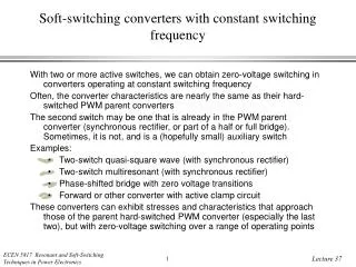
Time-Domain Analysis of Resonant and Soft-Switching Converters. Principles of state-plane analysis and averaging In a large number of cases, the circuit waveforms are not approximately sinusoidal

E N D
Time-Domain Analysis of Resonantand Soft-Switching Converters • Principles of state-plane analysis and averaging • In a large number of cases, the circuit waveforms are not approximately sinusoidal • The mechanisms of soft-switching PWM converters cannot be understood using the sinusoidal approximation • The mechanisms of switching loss in hard-switched PWM converters cannot be understood using the sinusoidal approximation • “Exact” time-domain analysis of these converters initially appears to be very complex, but is considerably simplified when certain analysis principles are employed (there are 4-5 logical leaps to be learned) • Goals of this part of the course: • learn the basic analysis principles • learn to analyze the basic soft-switching circuits and resonant converters • learn the physical properties of the most well-known soft-switching converters
Key Concepts • Averaging current (charge) and voltage (flux-linkages) over one switching period • Relating average current to change in tank capacitor charge, and relating average voltage to change in tank inductor flux linkages • Kirchhoff’s Laws in integral form • Steady-state tank capacitor charge balance and inductor volt-second (flux linkage) balance for resonant circuit waveforms • Normalization of voltage, current, time, and other quantities • The state plane trajectory of resonant tank waveforms • Examples: series and parallel resonant dc-dc converters • Examples: quasi-resonant, zero-voltage transition, and active-clamp converters • Examples: modeling switching loss in hard-switched converters having ringing waveforms
Averaging: Charge Arguments Averaging a terminal current of a (resonant) converter to find the dc or low-frequency component: where We will relate this charge to the change in charge on a tank capacitor within the converter
Averaging: Volt-Second,or Flux-Linkage, Arguments Averaging a terminal voltage of a (resonant) converter to find the dc or low-frequency component: where We will relate these volt-seconds to the change in flux-linkages in a tank inductor within the converter
Relating the tank capacitor ac voltageto the dc load current q = C (VCP – (–VCP)) = 2CVCP
Relating the tank inductor ac currentto the dc load voltage = L (ILP – (–ILP)) = 2LILP
Kirchhoff’s Laws in Integral Form: KCL KCL: sum of currents into a node = 0 Integrate over a time interval: net charge entering the node = 0 where
Integral KCL: Example By KCL, we know that i1 = iC + i2. Hence, where
Kirchhoff’s Laws in Integral Form: KVL KVL: sum of voltages around a loop = 0 Integrate over a time interval: net volt-seconds around the loop = 0 where
Integral KVL: Example By KVL, we know that v2 = v1 – vL. Hence, where