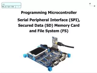
Serial Peripheral Interface (SPI)
Serial Peripheral Interface (SPI). SPI = Simple, 3 wire, full duplex, synchronous serial data transfer Interfaces to many devices, even many non-SPI peripherals Can be a master or slave interface 4 interface pins: -MOSI master out slave in -MIOS master in slave out


Serial Peripheral Interface (SPI)
E N D
Presentation Transcript
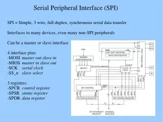
Serial Peripheral Interface (SPI) SPI = Simple, 3 wire, full duplex, synchronous serial data transfer Interfaces to many devices, even many non-SPI peripherals Can be a master or slave interface 4 interface pins: -MOSI master out slave in -MIOS master in slave out -SCK serial clock -SS_n slave select 3 registers: -SPCR control register -SPSR status register -SPDR data register
Serial Peripheral Interface (SPI) Full duplex, synchronous serial data transfer Data is shifted out of the master's (mega128) MOSI pin and in its MISO pin Data transfer is initiated by simply writing data to the SPI data register. All data movement is coordinated by SCK. Slave select may or may not be used depending on interfacing device. To get input data only you send “junk” data to SPDR to start the clock. master SPI device slave SPI device
Serial Peripheral Interface (SPI) Slave Select... use it carefully! In master mode: -SPI interface has no control of SS_n -User software has full control of SS_n (Port B, bit 0) -If configured as output, it’s a general purpose output -If configured as input, it must be held high, else you will enter slave mode We will use SPI in master mode, full duplex
Serial Peripheral Interface (SPI) SPI Control Register (SPCR) interrupt enable: if set, interrupt occurs when SPI interrupt flag and global interrupt enable are set clock rate (in SPSR) spi enable: if set, SPI interface is enabled SPI2X SPR1 SPR0 SCLK 0 0 0 fosc/4 0 0 1 fosc/16 0 1 0 fosc/64 0 1 1 fosc/128 1 0 0 fosc/2 1 0 1 fosc/8 1 1 0 fosc/32 1 1 1 fosc/64 data order: if set, LSB is transmitted first master/slave select: if set, SPI in master mode clock polarity: '0' SCK low in idle '1' SCK high in idle clock phase: '0' leading edge sample, trailing edge setup '1' leading edge setup, trailing edge sample
Serial Peripheral Interface (SPI) SPI Status Register (SPSR) reserved bits interrupt flag: set when serial transfer is complete write collision: set if SPDR is written during a receive transfer 2x clock rate: if set, doubles clock rate in master mode SPI Data Register (SPDR) SPDR is a read/write register used for data transfer. Writing SPDR sends data out MOSI. Reading SPDR gets the data that was clocked into MISO.
Serial Peripheral Interface (SPI) Mega128 LCD interface SCK, PB1 LCD strobe, PF3 MOSI, PB2 9-bit shift register enable pulse generator
Serial Peripheral Interface (SPI) SPI Application - Code /*********************************************************************/ // spi_init //Initializes the SPI port on the mega128. Does not do any further //external device specific initializations. /*********************************************************************/ void spi_init(void){ DDRB = DDRB | 0x07; //Turn on SS, MOSI, SCLK (SS is output) SPCR |= (1<<SPEN) | (1<<MSTR); //spi enabled, master, low polarity, msb 1st SPSR |= (1<<SPI2X); //run at i/o clock div 2 }//spi_init /***********************************************************************/ // digi_pot_send //Sends command and data to the digital pot. SPI device chip select is //active low and is connected to port F bit 2. Total of 16 bits are sent. //One byte for control and one byte as data passed in. /***********************************************************************/ void digi_pot_send(uint8_t data){ PORTF &= 0xFB; //port F bit 2, assert active low SPDR = 0x13; //send command byte (fixed value) while (bit_is_clear(SPSR,SPIF)) {} //wait till data is sent out SPDR = data; //send data byte while (bit_is_clear(SPSR,SPIF)) {} //wait till data is sent out PORTF |= 0x04; //port F bit 2, deassert to logic high } //digi_pot_send
Serial Peripheral Interface (SPI) Typical SPI IC (MCP42010)
Serial Peripheral Interface (SPI) 74HC595 – A perfectly fine SPI peripheral
Serial Peripheral Interface (SPI) What if you want only to read the SPI port? To get the SPI clock to run, a "dummy" write is made to the SPISPDR register. This starts the clock running so the data on MISO is brough into the uC. If no peripherals are selected, the outgoing data will be ignored. If you are clever, you can send data out and bring data in at the same time. /*********************************************************************/ // spi_read //Reads the SPI port. /*********************************************************************/ uint8_t spi_read(void){ SPDR = 0x00; //"dummy" write to SPDR while (bit_is_clear(SPSR,SPIF)){} //wait till 8 clock cycles are done return(SPDR); //retrun incoming data from SPDR }//read_spi
Serial Peripheral Interface (SPI) 74HC165 – Another fine SPI peripheral
Serial Peripheral Interface (SPI) SPI “Gotchas” “Now my board won’t program.” SPI shares SCK with programming interface. If it won’t program anymore, you likely messed up SCK. “SPI acts totally wierd.” Often a symptom of SS_n being configured as an input and being left to float or allowed to go high. SPI goes in and out between slave and master modes. “I never get data to the SPI device.” Is clock correctly oriented ? Did you assert the device chip select? (hint: put SPI write inside a “tight” loop and check with scope. Watch SCK, data, and chip select) "SPI device interactions:" When programming, the programmer first does a chip reset. When the mega128 resets, all pins are set to input with high impedance (floating). If a SPI device is on the SPI bus, it's chip-select may float low and enable the device, and SPI data will crash the programming data. Adding a pull-up resistor to chip selects will solve this problem.