Digital Data and Digital Signal
350 likes | 441 Vues
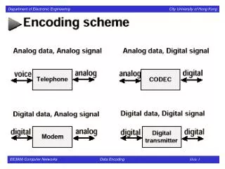
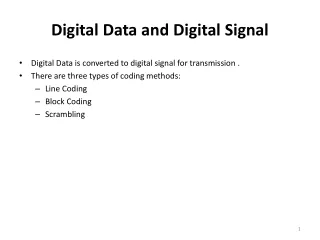
Digital Data and Digital Signal. Digital Data is converted to digital signal for transmission . There are three types of coding methods: Line Coding Block Coding Scrambling. Characteristics of Encoding Schemes. No. of signal levels Bit rate and baud rate DC component Signal Spectrum

Digital Data and Digital Signal
E N D
Presentation Transcript
Digital Data and Digital Signal • Digital Data is converted to digital signal for transmission . • There are three types of coding methods: • Line Coding • Block Coding • Scrambling
Characteristics of Encoding Schemes • No. of signal levels • Bit rate and baud rate • DC component • Signal Spectrum • Noise Immunity • Error Detection • Synchronization • Cost of Implementation
No. of Signal Levels • The Nyquist bit rate formula defines the theoretical maximum bit rate for a noiseless channel • Bitrate = 2 x Bandwidth x Log2 L • Where, • Bitrate is the bitrate of the channel in bits per second • Bandwidth is the bandwidth of the channel • L is the number of signal levels.
Bit rate and Baud rate Bit Rate • It is the number of bits transmitted in one second. • It is expressed as bits per second (bps). Baud Rate • It is the rate of Signal Speed, i.e the rate at which the signal changes. • A digital signal with two levels ‘0‘ & ‘1‘ will have the same baud rate and bit rate. • Baud Rate = Bit Rate / No. of Bits per signal. • In the digital transmission, bit rate should be higher than the baud rate (i.e. lower than the bit rate)
DC Component • The average amplitude of a signal is nonzero. • This creates what is called a direct current (DC) component (a component with zero frequency). • DC component in a signal is not desirable because the DC component does not pass through some components of a communication system such as a transformer. • This leads to distortion of the signal and may create error at the output. • The DC component also results in unwanted energy loss on the line.
Signal Spectrum • Different encoding of data leads to different spectrum of the signal. It is necessary to use suitable encoding technique to match with the medium so that the signal suffers minimum attenuation and distortion as it is transmitted through a medium. As the coding is done to make more bits transmit on a single signal, the bandwidth used is much reduced. Power efficiency • For a given bandwidth and a specified detection error probability, the transmitted power for a line code should be as small as possible. Noise Immunity • Noise is defined as an unwanted data. When some electromagnetic signal gets inserted during the transmission, it is generally called as a Noise. Due to Noise it is difficult to retrieve the original data or information.
Error Detection and Correction capability • Error Detection uses the concept of redundancy, which means adding extra bits for detecting errors at the destination. They can easily be detected. Cost of Implementation • To minimize cost of implementation.
Synchronization • In order to receive the signals correctly, the receivers bit intervals must correspond exactly to the senders bit intervals. • The clock frequency of the transmitter and receiver should be the same. • If the clock frequency at the receiver is slower or faster than the bit intervals are not matched and the received signal is different than the transmitted one. • Different Methods to achieve synchronization : A separate line used for clock information, but it very costly due to a separate link increase wire expenditure. • Secondly, Regenerate clock at the receiver end with special hardware (phase lock loop).
Types of Line Coding • There are 3 types of Line Coding • Unipolar • Polar • Bi-polar Unipolar Signaling • Unipolar signaling is also called as On-Off Keying or simply OOK. • The presence of pulse represents a 1 and the absence of pulse represents a 0. • There are two variations in Unipolar signaling − • Non Return to Zero (NRZ) • Return to Zero (RZ)
Unipolar Non-Return to Zero (NRZ) • In this type of unipolar signaling, a High in data is represented by a positive pulse called as Mark, which has a duration Tb equal to the symbol bit duration. A Low in data input has no pulse. • The following figure clearly depicts this.
Advantages • The advantages of Unipolar NRZ are − • Simplicity in implementation. • A lesser bandwidth is required. • Bit rate same as data rate. • Disadvantages • The disadvantages of Unipolar NRZ are − • No error correction done. • Low Noise immunity. • High Crosstalk • DC component present. • Loss of synchronization is likely to occur (especially for long strings of 1s and 0s).
Unipolar Return to Zero (RZ) • In this type of unipolar signaling, a High in data, though represented by a Mark pulse, its duration T0 is less than the symbol bit duration. Half of the bit duration remains high but it immediately returns to zero and shows the absence of pulse during the remaining half of the bit duration. • It is clearly understood with the help of the following figure.
Advantages • The advantages of Unipolar RZ are − • It is simple. • The spectral line present at the symbol rate can be used as a clock. Disadvantages • The disadvantages of Unipolar RZ are − • No error correction. • Occupies twice the bandwidth as unipolar NRZ. • The signal droop is caused at the places where signal is non-zero at 0 Hz. This means that AC coupling will result in distortion of the transmitted pulse shapes. AC coupled transmission lines typically behave like high-pass RC filters and the distortion takes the form of an exponential decay of the signal amplitude after each transition • DC component present. • Loss of synchronization is likely to occur (especially for long strings of 0s).
Polar Signaling • There are two methods of Polar Signaling. They are − • Polar NRZ • Polar RZ • Polar NRZ • There are two NRZ schemes • NRZ –L (Non Return Zero-Level) • NRZ-I (Non Return Zero-Inversion) • In NRZ-L the level of the voltage determines the value of the bit. In NRZ-I the inversion or the lack of inversion determines the value of the bit. • In NRZ-L, 1’s is the low level and 0’s is the high level. • In NRZ-I, for each 1 in the bit sequence, the signal level is inverted. • A transition from one voltage level to the other represents a 1.
Advantages • The advantages of Polar NRZ are − • It is simple. • No low-frequency components are present. Disadvantages • The disadvantages of Polar NRZ are − • No error correction. • No clock is present. • The signal droop is caused at the places where the signal is non-zero at 0 Hz.
Polar RZ • In this type of Polar signaling, a High in data, though represented by a Mark pulse, its duration T0 is less than the symbol bit duration. Half of the bit duration remains high but it immediately returns to zero and shows the absence of pulse during the remaining half of the bit duration. • However, for a Low input, a negative pulse represents the data, and the zero level remains same for the other half of the bit duration. The following figure depicts this clearly.
Advantages • The advantages of Polar RZ are − • It is simple. • No low-frequency components are present. Disadvantages • The disadvantages of Polar RZ are − • No error correction. • No clock is present. • Occupies twice the bandwidth of Polar NRZ. • The signal droop is caused at places where the signal is non-zero at 0 Hz.
Bipolar Signaling • This is an encoding technique which has three voltage levels namely +, - and 0. Such a signal is called as duo-binary signal. • An example of this type is Alternate Mark Inversion (AMI). For a 1, the voltage level gets a transition from + to – or from – to +, having alternate 1s to be of equal polarity. A 0 will have a zero voltage level. • Even in this method, we have two types. • Bipolar NRZ • Bipolar RZ • From the models so far discussed, we have learnt the difference between NRZ and RZ. It just goes in the same way here too. The following figure clearly depicts this.
Advantages • Following are the advantages − • It is simple. • No low-frequency components are present. • Occupies low bandwidth than unipolar and polar NRZ schemes. • This technique is suitable for transmission over AC coupled lines, as signal drooping doesn’t occur here. • A single error detection capability is present in this. Disadvantages • Following are the disadvantages − • No clock is present. • Long strings of data causes loss of synchronization.
Biphase Encoding • There are two types of biphase encoding schemes • Manchester • Differential Manchester
Manchester Encoding • In Manchester code the mid bit transition serves as a clocking mechanism and also as data. • Low to high represents a 1. • High to low represents a 0.
Differential Manchester • Presence of transition in the beginning of a bit represent a 0. • Uses inversion in the middle of each bit for synchronization.
Characteristics • Two levels • No DC components • Good Synchronization • Higher bandwidth due to doubling of bit rate with respect to data rate.
Scrambling Schemes • Extension of Bipolar AMI • Used in case of long distance applications because for short distance, bandwidth is not important for transmission. Goals • No DC components • No long sequences of 0 level line signal • No increase in bandwidth • Error detection capability • Examples : B8ZS, HDB3
B8ZS (Bipolar with 8 zero substitution) • The Limitation of bipolar AMI is overcome in B8Zs. Commonly used in North America, Eight consecutive zero level voltages are replaces by the sequence • A sequence of eight 0’s is replaced by 000+-0-+, if the previous pulses was positive • A sequence of eight 0’s is replaced by 000-+0+-, if the previous pulses was negative
HDB3 (High Density bipolar 3 zero) • Another alternative, which is used in Europe and Japan • It Replaces a sequence of 4 zeros by a code as per the rule given in the below table
Characteristics • Three Levels • No DC components • Good Synchronization • Well Suited for long distance transmission over long distance.