Optimizing Correlator Performance at VLBI Technology Workshop
250 likes | 276 Vues
This workshop discusses FPGA usage, signal flow, and correlator engines at the Third International VLBI Technology Workshop, focusing on UniBoard setup, firmware changes, and processing configurations for high-resolution data analysis.

Optimizing Correlator Performance at VLBI Technology Workshop
E N D
Presentation Transcript
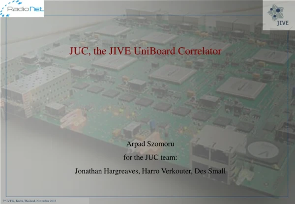
JIVE UniBoard Correlator (JUC) Firmware 10 November 2014 Jonathan Hargreaves, JIVE Third International VLBI Technology Workshop
UniBoard FN0 Stratix IV FPGA 2x 4GB DDR3 BN0 Stratix IV FPGA 2x 4GB DDR3 Backplane /Breakout 3x CX4 SFP+ Cage 3x 10GbE ports FN1 Stratix IV FPGA 2x 4GB DDR3 BN1 Stratix IV FPGA 2x 4GB DDR3 Backplane /Breakout 3x CX4 SFP+ Cage 3x 10GbE ports FN2 Stratix IV FPGA 2x 4GB DDR3 BN2 Stratix IV FPGA 2x 4GB DDR3 Backplane /Breakout 3x CX4 SFP+ Cage 3x 10GbE ports FN3 Stratix IV FPGA 2x 4GB DDR3 BN3 Stratix IV FPGA 2x 4GB DDR3 Backplane /Breakout 3x CX4 SFP+ Cage 3x 10GbE ports Third International VLBI Technology Workshop
JUC Signal Flow FNs do station based processing: Delay and Phase correction, channelization BNs contain the correlator engines Third International VLBI Technology Workshop
FPGAs like a simple life • Leave complex tasks to the control software • Run-time options consume real resources • Some modes can be supported by changing the firmware Third International VLBI Technology Workshop
FPGAs like a simple life • Leave complex tasks to the control software • Run-time options consume real resources • Some modes can be supported by changing the firmware • Aim is to support the most common modes for continuum processing Third International VLBI Technology Workshop
Correlator Engine • One BN correlator engine calculates 2112 products from 64 input streams • The processing bandwidth is 16MHz per BN 0 32 dual polarization stations 16MHz 2112 products 1024 frequency bins 15.625kHz spectral resolution 31 0 31 Third International VLBI Technology Workshop
BN Correlator Engine • All 2112 products are always computed – the control computer selects which ones to export 0 32 dual polarization stations Exported Products 16MHz 2112 products 31 0 31 Control computer sets a table of products to export Third International VLBI Technology Workshop
BN Correlator Engine • One UniBoard has four BN correlator engines • Total processing bandwidth is 64MHz => 32 stations at 512Mbps 0 32 dual polarization stations Exported Products 16MHz 2112 products 31 0 31 Third International VLBI Technology Workshop
BN Correlator Engine • Control software can configure a 16 station, 1Gbps correlator 0 32 dual polarization stations Exported Products 16MHz 2112 products 31 0 31 Third International VLBI Technology Workshop
BN Correlator Engine • … or an 8 station 2Gbps correlator 0 32 dual polarization stations Exported Products 16MHz 2112 products 31 0 31 Third International VLBI Technology Workshop
BN Correlator Engine • Processing bandwidth increases linearly with the number of UniBoards 0 0 0 0 0 0 0 16MHz 2112 products 16MHz 2112 products 16MHz 2112 products 16MHz 2112 products 16MHz 2112 products 16MHz 2112 products 16MHz 2112 products 31 31 31 31 31 31 31 0 0 0 0 0 0 0 31 31 31 31 31 31 31 Third International VLBI Technology Workshop
Channelization Polyphase filterbank weights can be re-loaded at run-time. Default is Blackman Harris Default mode is four 16MHz input sub-bands per station Channelized frequency bin size is 15.625kHz 2048 point FFT 2048 point FFT 2048 point FFT 2048 point FFT 6 taps pre-filter 6 taps pre-filter 6 taps pre-filter 6 taps pre-filter Sub-band a 1024 frequency bins BN0 1024 frequency bins Sub-band b BN1 Sub-band c 1024 frequency bins BN2 0 Sub-band d 1024 frequency bins BN3 Third International VLBI Technology Workshop
Sub-bands narrower than 16MHz • Lower bandwidths can be processed without changing the firmware • The spectral resolution increases • Pre-recorded data can be processes faster than real-time Third International VLBI Technology Workshop
Sub-bands wider than 16MHz … the FN firmware image has to change (but not the BN) Under test: Two 32MHz input sub-bands per station Channelized frequency bin size remains15.625kHz Upper 1024 bins BN0 Sub-band a 4096 point FFT 6 taps pre-filter Lower 1024 bins BN1 Upper 1024 bins BN2 0 Sub-band b 4096 point FFT 6 taps pre-filter Lower 1024 bins BN3 Third International VLBI Technology Workshop
Sub-bands wider than 16MHz … the FN firmware image has to change Under consideration: Channelized frequency bin size remains15.625kHz One 64MHz input sub-bands per station 1024 bins BN0 1024 bins BN1 Sub-band a 8192 point FFT 6 taps pre-filter 1024 bins BN2 0 1024 bins BN3 Third International VLBI Technology Workshop
Mixed Modes Possible by configuring the four FNs with different firmware abcd abcd 4 x 16MHz 4 x 16MHz FN0 FN1 Frequency bins to the back node correlator engines ab FN2 2 x 32MHz FN3 a 1 x 64MHz Third International VLBI Technology Workshop
Integration Time • Set at run-time in units of FFTs • One FFT is 64us • Range is approx. 0.022-1 s • Upper limit is due to memory available for corner-turning in the BN • Lower limit is due to the volume of output Third International VLBI Technology Workshop
Input Data Format • VDIF only • Tested with a frame length (payload) of 5000 bytes • Other frame lengths will be supported provided: • There is an integer number of frames in one second • The frames are a multiple of 8 bytes • Currently only 2-bit sampling • 1-bit will be supported shortly • 4 and 8-bit will be added as needed • Lower side bands are ‘converted’ to upper at the input Third International VLBI Technology Workshop
Delay and Phase Correction • The control computer sends a set of quadratic polynomial coefficients for each integration • Delay and phase coefficients are 48-bit and 64-bit integers respectively. This is enough precision to remain valid over the maximum 1 second integration. • The delay polynomial is evaluated at the start of the integration, and thereafter every FFT • The phase polynomial is evaluated every sample Third International VLBI Technology Workshop
Delay and Phase Correction • Integer delay is used to look up the first sample at the start of integration • Fractional delay (to 1/256th sample) is converted to phase at the band centre and applied after the FFT • Phase model is applied continuously using a quadrature mixer at the filterbank input DDR Pre Filter Structure Packet Receiver ETH Switch 10Gb-Eth Mixer FFT Normalize Framer FBI Mesh 3 1 2 Delay Model Control Computer 1Gb-Eth SOPC Third International VLBI Technology Workshop
Validity bits handle gaps in the data • 1 bit per VDIF frame stored in FN • A whole FFT is invalid if any contributing data are invalid • First six FFTs in an integration are invalid because pre-filter structure is filling up • Invalid FFTs are substituted by zeros so do not contribute to the products • One validity bit per FFT is carried across to BN and corner-turned with the data • Thirty-two bit validity accumulators calculate normalization factors for every product. Third International VLBI Technology Workshop
Current Developments • Commissioning with 4 x 16MHz band mode • Some stations have a phase drift over the scan • There are phase jumps between scans • Two bands of 32MHz bandwidth • Under test • Sample Statistics • Firmware written, needs integration and verification • VDIF Frame length • So far only 5000 byte frames have been tested • Mixed frame lengths can be supported with further work Third International VLBI Technology Workshop
Future Developments • Support 1, 4 and 8 bit sampled data • One bit can be supported by converting to 2 bit at the input • 4 and 8 bit to be added when needed • Pulsar Gating • One band of 64MHz bandwidth, mixed modes • Lower spectral resolution to reduce volume of output data • 1024 -> 64 points • UniBoard2 • Arria 10 (20nm) version should double throughput • Stratix 10 (14nm) version up to 8x the throughput Third International VLBI Technology Workshop
Hierarchical Design Front Node Back Node Floor Plan Physical Design