Download
1 / 37
370 likes | 569 Vues
Laboratory Experiments in Radiation Detection and Measurement. Radiation Types. Alpha: He nucleus, charge of +2 Beta: Electron, charge of -1 or +1 Photons: Electromagnetic radiation,

E N D
Laboratory Experiments in Radiation Detection and Measurement
Radiation Types • Alpha: He nucleus, charge of +2 • Beta: Electron, charge of -1 or +1 • Photons: Electromagnetic radiation, X-rays come from de-excitation of electrons and are atomic in origin while gamma rays come from de-excitation of the nucleus and are nuclear in origin, no charge, no mass • Neutron: Neutral particle • Proton: Particle with charge of +1, or H nucleus • Fission fragments and recoil atoms are charged atoms • Mesons are charged particles with ~270 x mass of electron
Radioactive Decay • Alpha Particle • He nucleus tunnels out of nucleus, discrete energy • Beta Minus Particle • Neutron decays to proton, beta minus particle (electron) and anti-neutrino, beta particle has energy up to a maximum value • Beta Plus Particle • Proton decays to neutron, beta plus particle (positively charged electron) and neutrino, positron has energy up to a maximum value • Electron Capture • Atomic electron is captured by nucleus and combines with a proton to form a neutron • Spontaneous Fission • Nucleus undergoes fission (heavy elements) • Delayed Neutron Emission • A few fission products undergo decay and emit neutrons • All of the above may produce gamma rays and x-rays
Charged Particle Interactions • Charged particle coulombic fields undergo collision with bound atomic electrons producing free electrons and charged atoms, or ions, with kinetic energy • Charged particles that pass near the nucleus are accelerated and produce x-rays of variable energy ranging up to the kinetic energy of the incident particle, this is also known as “Bremsstrahlung”
Photon Interactions • Photons, or x-rays and gamma rays, interact with matter to produce electrons, scattered photons, positrons and annihilation photons, and charged recoiling atoms by various interactions • Majority of energy from photon interactions is given to electrons, positrons, and photons • Annihilation photons result from combination of positron and electron at rest and have an energy of equal to the rest mass of an electron, 0.511 MeV
Neutron Interactions • A variety of absorption and capture interactions occur in which radioactive atoms, charged particles, photons, neutrons, recoil nuclei, and fission fragments are produced • (n,alpha) (n,gamma) (n, fission) (n, proton) (n, triton) • Scattering interactions may produce scattered neutrons of lower energy and a nucleus in an excited state. Upon nuclear de-excitation, photons are emitted • (n, n’) (n, n + gamma)
Neutron Activation • A = N [(1-exp(-ta)] exp(-td) • Where: • A = Activity (Bequerels) • N = number atoms of parent isotope • = neutron flux (n/cm2/sec) • = capture reaction cross section • = decay constant • ta/td = sample activation and decay times
Radiation Terms and Units • Dose • Energy deposited per unit mass • RAD = 100 ergs / gram, 1 Gy = 1 J / Kg = 100 RAD • Exposure • Ionization produced by photons in a mass of air, Roentgen = 2.58 E-4 Coulombs / Kg • Dose-equivalent • Tissue Dose X quality factor, Q X Modifying Factor, N • REM = RAD X quality factor, N is typically 1 1 Sv = 100 REM • Quality factor, Q, accounts for difference in the biological damage caused by different radiation types
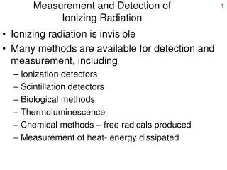
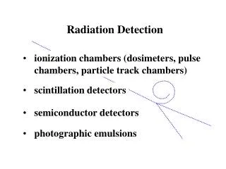
RADIATION DETECTORS • Gas filled detectors, e.g. Geiger-Mueller (GM) counters, Proportional counters, and Ion Chambers • Solid detectors, e.g. scintillators and semi-conductors • Liquid detectors, e.g. scintillators and chemical dosimeters • Dosimeters, e.g. film, thermoluminescent dosimeters • Ratemeters and counters (scalers)
GM Detectors • A fill gas is contained in a sealed tube of various shapes, sizes • Ionization occurs in the fill gas and in the detector wall material (wall is at ground potential and serves as the cathode) • Ions in the fill gas are accelerated and produce further ionization giving a pulse of maximum amplitude that is collected at the detector anode • GM detectors produce a full amplitude pulse (count) for any ion that enters the detector, so distinction between radiation types is not possible • GM detectors are very sensitive, inexpensive and rugged and therefore commonly used
Ion Chambers • Fill gas is air that may or may not be contained in a sealed chamber • Ionization occurs in the fill gas and in the detector wall material (wall is at ground potential and serves as the cathode) • Ions in the fill gas are collected at the detector anode and produce a pulse height proportional to the number of interactions, or ionization, occurring in the detection volume • Ion chambers are very accurate and allow distinction between radiation types based on pulse height
Solid Detectors • Scintillation crystals respond to radiation interactions by producing light. The light is then detected and converted to an electrical signal with a pulse height proportional to the radiation energy deposition rate. Scintillators are extremely sensitive to radiation and are often used for obtaining energy spectra. • Semi-conductors respond to radiation by producing electron-hole pairs. The pulse height proportional to the radiation energy deposition rate. Semi-conductors have superior resolution compared to scintillators are therefore a better choice for obtaining energy spectra.
Liquid Detectors • Scintillation detectors respond to radiation interactions by producing light which is then detected and converted to an electrical signal. The pulse height proportional to the radiation energy deposition rate. The sample and scintillator are mixed making alpha and beta particle detection very efficient. • Chemicals respond to radiation by changing oxidation state, which produces a change in spectrophotometry in which the peak size is proportional to the radiation energy deposition rate
Radiation Dosimeters • Film responds to photons by changing its lattice structure and upon development forms a latent image. The optical density is related to the radiation energy deposited. • Films may also be used to detect particles, which produce tracks upon being developed. The number and length of tracks are used to determine the amount and type of charged particles. • TLD are crystalline materials and respond to radiation by forming electron –hole pairs. Some e-h pairs are trapped at the time of formation in crystal imperfections. Upon addition of heat the trapped e-h pairs become mobile and release light which is then detected and related to the radiation energy deposited.
Radiation Sources • Consumer products (lantern mantles, welding rods, KI salt, smoke detectors) • Radon and its decay products (decay products are collected on furnace or vacuum cleaner filters – radon can be collected using charcoal canisters) • Exempt quantities of radioactive materials (under 10 CFR 30)
Radiation Sources • Naturally occurring sources; • H-3, C-14, K-40, Th-232, U-238 … radon • Cosmogenic and terrestial sources • Technology enhanced sources; • Mining of U producing higher levels of naturally occurring radioactive materials • Artificial sources; • Fission products, activation products, accelerated produced radioactive materials
Laboratories using GM Detector • Radiation type identification • Radiation shielding • Radiation source detection • Half-life determination • Detection efficiency • Detector resolving time • Backscatter factor
Identification of Radiation Type • GM detector wall thickness affects response. For the CDV-700 GM tube, moderate energy beta particles and all photons can be detected. • Open window = beta + photon • Closed window = photon • Open – closed window = beta NOTE: YOUR CDV-700 IS NOT CALIBRATED!
Radiation Shielding • Count rate, or mR/h reading, from a radiation source decreases as shielding is added. Beta radiation is easily shielded with paper, Al foil, or plastic. Photons are shielded best with high atomic numbered materials like Pb, W, or U although any material will work.
Radiation Shielding • Beta shielding and range are related. Beta particles have a defined range based on beta particle energy. Range equations are given in the attached file and on the next page. • Photon range has no endpoint in theory. Shielding is based on photon energy. R = R(0) exp (-uT) where R is response, u is the linear attenuation coefficient. u is a function of photon energy for a given material.
Radiation Shielding • Place source 2 inches away from open window GM counter for beta particles • Maintain source-detector geometry and place materials of known thickness between the source and detector • The exact thickness where the GM detector response equals that of background occurs if the beta particles are completely shielded. This material thickness is the range. • For photons, use a closed window. Determine the thickness where the GM detector response, R, is half and also a tenth of the unshielded response, R(0). These are the half value layer (HVL) and tenth value layer (TVL), respectively. Determine and compare the the linear attenuation coefficients: • R/R(0) = exp (-uT) = 0.5 for HVL; u = -[ln 0.5/T] • R/R(0) = exp (-uT) = 0.1 for TVL ; u = -[ln 0.1/T]
Radiation Shielding • A curved line, or change in the shape of the line, indicates that more than one radiation energy is present, or multicomponent line. • For resolution, determine the shape of the high energy line (high thickness readings) and extrapolate back to lower energies (lower thickness readings). This produces a third, low energy line. • Extrapolate the low energy line to a zero reading to determine the range of the lower energy radiation
Radiation Source Detection • Perform instrument checks to verify operation • Determine background radiation level in an area known to be free of radiation sources • Survey area and items with open window • If elevated readings are found, survey with open and closed window. Record data.
Half-life Determination • Obtain source with half-life of minutes or days range • Set up source next to open window detector • Record detector reading and time. Repeat this step to obtain several data points. • Plot results on semi-log paper with detector readings on y-axis (log scale) and time on x-axis (linear scale) • Determine slope, m, which is also the decay constant; m = {ln[(y(1)] – ln[y(2)]}/[t(1) – t(2)] • Determine half-life using the slope (decay constant or λ); ln 2 = λT1/2 • Compare results to reported value for the source
Detector Efficiency • Used for detector calibration • Used in analysis of samples and sources • Used to determine detector sensitivity, or detection limits • Efficiency, E = cpm / dpm or counts per decay for a given radiation type and energy. E may also be expressed as counts per beta particle, counts per gamma photon, etc. by using the radiation yield, Y; E = cpm / dpm X 1 decay / Y
Detector Efficiency • For GM detectors, beta efficiency is affected by distance and beta particle energy • Typical efficiencies for CDV-700 for moderate to high energy beta particles range between 0.01 to 0.05 c/d
Detector Resolving Time • Resolving time is used to correct for count rate, cpm, losses. These losses occur because the counting rate exceeds the ability of the detector to process the pulses. • Obtain two sources, one of low activity and a second of higher activity • Place the first source near the open window and record the cpm reading, or R(1) • Place the second source near the open window and record the cpm reading, or R(2) • Place the both sources near the open window and record the cpm reading, or R(1+2)
Detector Resolving Time • Calculate detector resolving time as follows: t = [R(1) + R(2) – R(1+2)] / [2 R(1)R(2)] • Typical GM detector resolving times, t, are hundreds of microseconds, us (e.g. 100 us = 1.67 E-6 minutes) • R = R(0) / [1-R(0) t], if R(0) is cpm, use t in minutes • R(0) is observed count rate, in cpm • R is the true count rate, in cpm
Backscatter Factor • Backscattering is the deflection of radiation by scattering processes through angles greater than 90 degrees with respect to the original direction • Alpha radiation travels in a straight line motion while beta particles will alter their path direction significantly upon interacting with matter. As a result, backscattering may be significant for beta radiation sources counted by a GM detector depending on the beta particle energy and source backing material. • As a result of beta particle backscattering, the detector count rate increases • Backscatter factors may be as high as 40% • Corrections for backscattering may be necessary for analytical measurements
Backscatter Factor • Obtain a high energy beta emitting radioactive source in liquid form • Uniformly disperse and evaporate on an extremely thin layer of material (saran wrap, scotch tape, mylar). Also cover the source with a thin layer of material to prevent the spread of contamination. • Place the GM open window tube near the source and record the cpm reading, C(0) • Place additional backing material of known thickness underneath the source (minimize air gaps by using adhesive tape or epoxy) and record the cpm reading, C • Continue the previous step until a maximum cpm reading is observed. This is the saturation point, which is approximately 0.3 times the beta particle range. • The linear thickness of a particular material to produce backscattering is approximately proportional to the reciprocal of the density of the material • If interested, repeat using other materials and observe the change on backscattering. Their should be a dependence on atomic number. • % Backscatter = [C – C(0)/C(0)] x 100 C is cpm with backing material, C(0) is cpm with minimal backing