Download
1 / 42
470 likes | 955 Vues
Byung Jin Park Prof. Chong Nam Chu School of Mechanical and Aerospace Engineering Seoul National University, Korea. Microfabrication by Electrochemical Machining and Deposition. September 9, 2004. Characteristics of Micro-ECM. No tool wear (vs. EDM, Micro end milling)

E N D
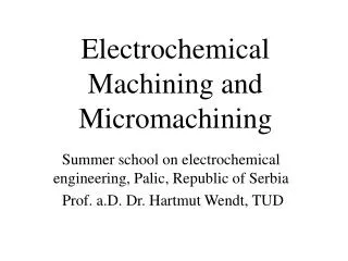
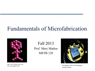
Byung Jin Park Prof. Chong Nam Chu School of Mechanical and Aerospace Engineering Seoul National University, Korea Microfabrication by Electrochemical Machining and Deposition September 9, 2004
Characteristics of Micro-ECM • No tool wear (vs. EDM, Micro end milling) • No mechanical stress (vs. Micro end milling) • No heat affected zone (vs. EDM, Laser beam machining) • Excellent surface quality • 3D complex shape (vs. Lithography) • Versatility of materials: metal, conductive polymer, graphite, semiconductor, etc. (vs. Lithography) • Low cost (vs. Lithography, Ion beam machining, LIGA) • Good productivity (vs. AFM/STM manipulation, Ion beam machining)
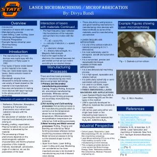
Micro-tool fabrication • Electrochemical etching • Wire electrical discharge machining Research Contents Electrochemical machining • Micro-hole • Micro-groove • Micro-mold Electrochemical deposition • Micro-column • Micro-spring • Micro patterning
DC power supply PMAC controller Z - stage PC Tungsten carbide Feeding direction Pt wire H SO s olution 2 4 Electrochemical Etching • Electrochemical etching of WC rod (high rigidity & high hardness) • Electrolyte: 1.5 M H2SO4 solution • Shaft size, shape, and surface quality according to electrolyte concentration, applied voltage, etching time, etc. Schematic diagram of the ECE system
Micro-tool Fabricated by Electrochemical Etching 30 mm 4 mm
Micro-tool Fabricatedby Wire Electrical Discharge Machining Wire Electrical Discharge Machining (WEDM)
Principle of Electrochemical Machining/Deposition • Machining: anodic dissolution • Deposition: cathodic reduction • Electric field localization at tool-end region using ultra short pulses Tool Electrolyte Workpiece
Tool Rs_large Cd Rp Rs_small Workpiece Electrochemical Cell Model Electrical double layer Equivalent circuit model of electrochemical cell
T Tool Rs_large Cd Rp Rs_small Workpiece Principle of Electric Field Localization Using Ultra Short Pulses Tip-end of a tool: due to small electrolyte resistance (Rs_small), the time constant (1) for double layer charging is small. Side of a tool: due to large electrolyte resistance (Rs_large), the time constant (2) for double layer charging is large. Dissolution region can be localized under the condition of 1 <T<< 2 (T: pulse on-time) d :machinable distance r : specific electrolyte resistivity CDL: specific double layer capacity (~10 mF/cm2) t : time constant for DL charging t = r d CDL
Experimental Equipments TARBO 8551 Pulse Generator (50MHz) TDS 3034 Oscilloscope (300MHz,Tektronix) Pulse Generator - + Oscilloscope Tool Balance Electrode Workpiece PMAC Controller Schematic diagram of pulsed ECM system
Balance Electrode Because of very small contact area between the tool and the electrolyte, the voltage drop is rather larger than the voltage drop between electrolyte and substrate. By implementing the balance electrode (Pt plate) connected to the cathode, we can machine the holes in the transpassive region. - Minimize the bubble generation, boiling. - Prevent the Cr oxide layer forming. – Vtool Cr passive layer (chromium oxide) is formed on the hole surface. (Cr passivation region: -300 mV~1000 mV) Vwork + surface covered with chromium oxide layer after machining without balance electrode
Experiments for Dissolution Localization Feeding 10mm into the workpiece f 30 mm 10 mm Machining for a specific time R 5 mm Measuring the hole diameter at the top surface
Localization According to Pulse On/Off-time and Applied Voltage DC 3.5V 5.0 V, 2 s period 6.0 V, 2 s period 6.0 V, 40 ns on-time
Hole Size & Shape According to Pulse Off-time (a) 200 ns period f 30 mm tool, 6.0 V, 40 ns on-time, 30 min. machining time, 55 mm diameter. (b) 500 ns period f 30 mm tool, 6.0 V, 40 ns on-time, 30 min. machining time, 49 mm diameter. (c) 2 s period f 30 mm tool, 6.0 V, 40 ns on-time, 30 min. machining time, 47 mm diameter.
Step Hole Two Step Condition Back Front f 30 mm tool 6.5 V, 120 ns/2 s 40 min machining time 85 mm depth 84 mm diameter f 30 mm tool 5.0 V, 30 ns/2 s 20 min machining time 15 mm depth 28 mm diameter Step 1: Step2: This process can be applied to fabricate the micro-punching dies and nozzles
The Sequence of Taper Generation 50 m tool, 7.5 V, 300 ns / 2 s, without balance electrode 20 mm depth De: 106 mm, Db: 52 mm Taper: 53˚ 50 mm depth De: 126 mm , Db: 66 mm Taper: 31˚ 70 mm depth De: 132 mm , Db: 72 mm Taper: 23˚ 100 mm depth (Through hole) De: 140 mm , Db: 108 mm Taper: 9˚ Sudden reduction in taper just after perforation • Over-cut generation • Large taper Gradual decrease in taper angle due to increased machined depth
Taper Reduction Technique in Blind Hole Machining Ehigh : Entrance, High Condition E2 Elow : Entrance, Low Condition E1 ΔD2 Bhigh : Bottom, High Condition B2 ΔD1 Blow : Bottom, Low Condition B1 Localization Curve ΔD1> ΔD2 T T Tfeed Tdwell ΔD1 ΔD2 Entrance Machining start E1 E2 Voltage up On-time up T_dwell T T_feed B2 Bottom Machining start B1
Taper Reduction by the Proposed Method (a) Continuous condition : 6.0 V, 80 ns on-time, 2 s period, 20 min machining time 60 mm depth, 49 mm diameter and 12.7˚ taper angle. (b) Two-step condition : 1st step: 6.0 V, 80 ns on-time, 2 s period, 30 min machining time 2nd step: 7.0 V, 100 ns on-time, 2 s period, 5 min machining time 60 mm depth, 52 mm diameter and 4.8˚ taper angle. f20 mm tool, 100 mm thickness 304 SS
Micro-hole (1) t 100 ㎛ 304 SS, 0.1 M H2SO4, f 4 mm tool (a) Entrance: 13.6 mmin diameter (b) Exit: 10.5 mm in diameter Two step condition : 1st step: 4.8 V, 32 ns/2 ms, 50 min machining time. 2nd step: 5.2 V, 32 ns/2 ms, 10 min machining time. f13.6 mm / f10.5 mm, 0.9˚ taper angle, A/R 8.3
Micro-hole (2) t 100 mm 304 SS, 0.1 M H2SO4, f4 mm tool (a) Entrance: 20.3 mm in diameter (b) Exit: 18.1 mm in diameter Two step condition : 1st step: 5 V, 30 ns/2 ms, 25 min machining time. 2nd step: 5.5 V, 30 ns/2 ms, 10 min machining time. f20.3 mm / f18.1 mm, 0.6˚ taper angle, A/R 5.2
Micro-hole (3) t 20 mm 304 SS, 0.1 M H2SO4, f6 mm tool (a) Entrance: 8.0 mm in diameter (b) Exit: 7.3 mm in diameter f8.0 mm / f7.3 mm, 1.0 º taper angle and A/R 2.3 4.2 V, 21 ns/2 ms, 30 min machining time.
Micro-mold Fabrication by Electrochemical Milling • Material: • Stainless steel (304 SS) • Mold size: • 150 mm x 100 mm x 60 mm • Column size: • 30 mm x 20 mm x 60 mm 10-20 mm 20-30 mm
Layer-by-layer Machining • Advantage • Electrolyte flushing for ion supply • Short machining time Machining gap according to machining time
Micro-mold Fabricated by Cylindrical Tool 6 V, 60 ns pulse on-time, 1 ms period
Machining Gap According to Tool Shape Cylindrical tool 6 V, 60 ns/ 1 ms ? Disk-type tool
Disk-type Electrode • Disk-type electrode • Material: WC • Disk diameter: 70 mm • Neck diameter: 20 mm • 100 V, 400 pF
10mm • Micro-mold (304 SS) • 6 V, 60 ns / 1 ms • Column size • Width: 30 mm • Height: 60 mm Micro-mold with a Vertical Column
Machining Gap According to Tool Shape Cylindrical tool Disk-type tool 6 V, 60 ns/ 1 ms
Micro-mold Fabricated by Disk-type Tool • Micro-mold (304 SS) • 6 V, 60 ns pulse on-time, 1 ms period • Column size • Width: 84 mm • Height: 80 mm
Electrochemical Milling Material: SS304 Electrolyte: 0.1 M H2SO4 Pulse: 6.0 V, 60 ns / 1 ms
Micro-groove (304 SS) 6 V, 60 ns/ 1 ms 45 mm width, 100 mm depth, 300 mm length 300mm Micro-groove
Micro-wall Micro-wall 304 SS, 6 V, 60 ns/ 1 ms 4 mm width 15 mm height
Electrochemical Wire Grooving Material: SS304 Wire: Pt wire Φ10 mmElectrolyte: 0.1 M H2SO4Pulse: 8.0 V, 400 ns / 1 ns Groove with 28mm width, 20mm depth
Cathode: Cu2+ + 2e– Cu Anode: 2H2O 4H+ + 4e– + O2 Electrochemical Deposition • Electrochemical deposition of Cu on Cu substrate • Electrolyte: 0.5 M CuSO4 + 0.5 M H2SO4 solution • Deposition size, shape, and structure according to applied voltage, and pulse duration • Electrochemical writing Pulse generator + - Pt-Ir tip 0.5 M CuSO4 0.5 M H2SO4 Oscilloscope Cu substrate PMAC controller Experimental set-up for electrochemical deposition
Effects of Applied Voltage & Pulse On-time on Deposition Deposited column diameter decreases as applied voltage increases since the growing rate is high under high voltage condition Dendritic structure is formed with short pulse on-time (< 250 ns /1 ms) Recommended condition Applied voltage: 3.0 ~ 3.5 V Column diameter according to applied voltage Pulse: 350 ~ 450 ns / 1 ms
Column Deposition 3.5 V, 450 ns/1 ms, f 7 mm dia., 24 mm height 4.0 V, 450 ns/1 ms, f 7 mm dia., 15 mm height
Column Array 3.5 V, 350 ns/1 ms, 70 mm height
Micro-spring 2.5 V, 450 ns/1 ms, 100 mm spring radius, 350 mm pitch
Micro Patterning (1) Pt-Ir tip Cu substrate 10 mm line width, 2.5 V, 400 ns/1 ms
Micro Patterning (2) Spiral, line width 15 mm, pitch 60 mm,2.0 V, 450 ns/1 ms, 10 mm line width, 2.5 V, 450 ns/1 ms
Conclusions • Micro-tool Fabrication • Electrochemical Etching • Wire Electrical Discharge Machining • Localization of Electrochemical Reaction Region, Using Ultra Short Pulses • Machining Gap Modeling, Tool Shape Design • Electrochemical Machining • Micro-hole • Micro-groove • Micro-mold • Electrochemical Deposition • Micro-column • Micro-spring • Micro patterning