Kinematic Couplings and Elastic Averaging
640 likes | 1.45k Vues
Kinematic Couplings and Elastic Averaging. Precision, Intelligent, Low Cost Interfaces with Medical Applications?.

Kinematic Couplings and Elastic Averaging
E N D
Presentation Transcript
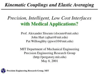
Kinematic Couplings and Elastic Averaging Precision, Intelligent, Low Cost Interfaceswith Medical Applications? Prof. Alexander Slocum (slocum@mit.edu)John Hart (ajhart@mit.edu)Pat Willoughby (pjwst10@mit.edu)MIT Department of Mechanical EngineeringPrecision Engineering Research Group (http://pergatory.mit.edu)May 8, 2001
Introduction Kinematic Coupling Basics Projects and Examples Exchangeability and Data Handling Potential Medical Applications? Demonstration
Overview of Common Coupling Methods Flexural Kin. Couplings Kinematic Constraint Pinned Joints No Unique Position Elastic Averaging Non-Deterministic Kinematic Couplings Kinematic Constraint Quasi-Kinematic Couplings Near Kinematic Constraint
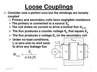
Exact Constraint (Kinematic) Design Exact constraint means a component has an equal number of constrained points to number of degrees of freedom If component is over constrained, clearance and high tolerances required to prevent premature failure or assembly incompatibility Kinematic design means that the motion is exactly constrained and geometric equations can be written to describe its motion Kinematic Couplings constrain components exactly, commonly providing repeatability of ¼ micron or on the order of parts’ surface finish Managing Hertz contact stresses is the key to successful kinematic coupling design
Hertz Contact Stress Heinrich Hertz, the mathematician famous for his work in the frequency domain, also created the first analytical solution for determining the stress between two bodies in point contact Exact constraint design often creates contact at single points, creating high stresses Creative solutions, such as canoe balls and quasi-kinematic couplings, help alleviate contact problems Heinrich Hertz 1857-1894
Load Capacity of Kinematic Elements • The “Canoe Ball” shape is the secret to the design • It acts like a ball 1 meter in diameter • It has 100 times the stiffness and load capacity of a normal 1” ball • It has 10 times the load capacity of a crowned-cone • The large shallow Hertzian zone is very repeatable US Patent 5,711,647
Canoe Ball Repeatability Measurements Coupling Measurement system
Quasi-Kinematic Couplings (QKC’s) Spherical Protrusion Groove Seat Side Reliefs • QKC Attributes and Characteristics: • • Surfaces of Revolution -> • Line Contact • • Weakly Over-constrained • • Sub-micron Repeatability • • Sealing Contact • • High Stiffness
QKC Function F or D dfinal d= 0 dinitial Block Bedplate • PROCESS: • • Mating force/displacement applied • • Ball & groove comply • • Brinell out surface finish • • Elastic recovery restores gap Application: Location of Engine Components
There are MANY other uses for Kinematic Couplings…. • The Kinematic Sheet Coupling was created for the Printed Circuit Board (PCB) industry • It provides 10x greater repeatability than traditional 4 pins-in-4-slots method
Example: Three-Tooth Couplings A semi-kinematic effect can be achieved by having three teeth each on two coupling halves mate at six points 3-5 micron repeatability can be obtained with this simple design Layton Hale at LLNL put crowns on one set of the teeth to create a nearly true kinematic three tooth coupling: 1 micron repeatability can be obtained with this simple design
Example: Magnet Preloading for Indicator Arm Preload MUST be repeatable Preload must be high and thus must NOT deform the rest of the structure Preload through the center of the kinematic elements with bolts Preload an instrument coupling with magnets Example: Kinematic coupling used to hold probe arm to an electronic indicator (US patent 4,574,625, assigned to Federal Products Corp.).
Current Projects for ABB IRB6400 Use kinematic couplings to enable quick-change modularity of industrial robots: • Measurement interface - repeatable attachment of a quick-calibration inclinometer device to the robot structure, small size and loading • Structural interface - repeatable and exchangeable attachment of the manipulator wrist to the remainder of the structure, medium size and loading • Factory interface - repeatable and exchangeable attachment of the manipulator to the factory floor, large size and extensive dynamic loading Require NO online calibration after module replacement
Measurement Interface: The Wonder Wyler • Device to calibrate angles of the six robot axes • Consists of two inclinometers at right angles • Measurements at six locations on robot • Adjusts robot to desired zero angles and recalibrates controller to these values
Design Goals Portable and compact device Secured coupling for both vertical and horizontal mounting using magnets Accurate and repeatable coupling to ±0.01 degrees Adaptable to various robot sizes Patent application for calibration method and device Inclinometer Spheres in Grooves
Structural Interface: Robot Wrist Replacement Z Y X • Replacement time - 30 to 60 minutes plus recalibration • Repeatability to ~ 1mm Robot Wrist Note: Robot is in Wrist Removal Position
Initial Design for Canoe Balls and Grooves on Wrist Design uses canoe balls shown earlier Short dashes show explosion of grooves and balls Yellow preload bolts pass through arm interface plate, canoe balls, and grooves. Bolts thread into holes on wrist plate.
Factory Interface: Robot Manipulator Mount Use kinematic locators between robot foot and floor-mounted baseplate, redefining the installation and replacement processes: • Calibrate production robots to a master baseplate at the robot factory • Install individual baseplates at the line site and calibrate directly to tooling • Measure couplings directly and predict interface error as a frame transformation • Reduces replacement error at tool (TCP) from 0.8 mm to 0.10 mm – no path touch-up required Benefits $10,000 per minute of downtime saved
Factory Interface Coupling Concepts Compare long-term static and dynamic performance of kinematic interfaces for the base: (1) Canoe ball couplings (2) Three-pin coupling (3) Standard quasi-kinematic couplings (4) Low-cost extruded quasi-kinematic couplings
Calibration for Exchangeability Modular components demand blind, accurate exchangeability – supplants traditional adequacy of high repeatability Solution: Kinematic coupling with integrated measurement feature • Measure hemispherical features on each ball and groove • Short measurement loop between feature and kinematic contact points minimizes variational error • Calibration software finds deterministic error transformation between interface frames
Standard Representation Cost Error Standardize kinematic interfaces for wide-scale implementation • Deterministic behavior = discrete parameter representation - Repeatability = f(material, type) - Exchangeability = f(manufacturing tolerances, type) - Load capacity = f(geometry, material) - Long-term performance = f(material, type, load condition) - (etc)…. • Standardized interface is easy to encode for calibration and efficient parameter transmission • Offer a cost vs. accuracy “menu” to customers – pick standard interface suited to application = desired accuracy at minimum cost
Intelligent Data Handling Couple kinematic interfaces with short-range wireless communications technologies to build intelligent systems • Replace calibration diskettes with RFID chips, and proximity detection initiates : - Auto-identification of installed module (ID, type, and location) - Auto-calculation of error transformations when a model is replaced • Encode measurement data on parts in process • Correct for major variation with active kinematic fixtures • Transponders in machines act as peer-to-peer repeaters, extending the wireless network factory-wide with minimal cabling
Wireless Concept: Measurement Tool Wireless tool for instant dimensional troubleshooting in automotive assembly stations:
Application: Modular Microscope Working with U. Illinois Laboratory for Fluorescence Dynamics (LFD) on development of modular biological instrumentation: Traditional microscopes are inadequate for single-molecule experiments (e.g. force measurements during DNA protein binding), which demand: • Nanometer-scale optical resolution • Flexibility to accept widely different optical modules and instrumentation peripherals • Ability to reconfigure the optical setup without re-calibration • Structural resistance to vibration and acoustic noise • Stability of the optical environment within nanometers over hour-long experiments
Modular Kinematic Solution Modularize the structure using kinematic canoe locators: • Stable under thermal disturbances: - Rings direct heat to angular uniformity - Couplings act as thermal isolators - Design permits uniform axial and radial expansion • 0.1 micron repeatability of kinematic couplings makes re-alignment automatic • Optics can be attached to pre-calibrated replacement modules, simplifying experimental setup • Smaller rings are less expensive to fabricate than a single, high-precision column
Example: Compliant Kinematic Couplings • How can high repeatability be obtained without tipping instability? • Decouple the FRS • 1st achieve kinematic coupling • 2nd clamp surfaces together while allowing the kinematic elements to translate Not Flexed • Components to Design in CKCs: • Clamping Load / Friction / Mated Surface • Joint Location • Compliant Members • Kinematic Interface Flexed *U.S. Patent 5, 678, 944
Example: Kinematic Wavy Spring Washer • How to achieve compliant kinematic coupling effect for very low cost? • Form the elements into spring steel to form a Kinematic Wavy Spring Washer • Enables alignment while providing compliance between elements, OR • Enables kinematic coupling between elements with simple Vee grooves • Application of preload allows gap to close to create face-to-face loading condition for very high load capacity • ABB patent pending
Example: Kinematic Fluid Coupling (KFC) The KFC utilizes the Hertz contact area as a precision metal-to-metal seal for fluid or electrical connections US Patent #5,683,118
Potential Medical Applications What do you think? • - Is there a need for rapidly precisely coupled medical instruments? • What about a robot with changeable end effectors that is coupled to an MRI unit? • ……………..
Conclusion: Know Your Constraints! “Kinematic Design”, “Exact Constraint Design”…..the issue is: KNOW what is happening in the system Manage forces and deflections Know when “Elastic Averaging” should be used Know when “Kinematic Design” should be used To be robust and well-engineered, systems MUST be subject to a sensitivity analysis: Accuracy and repeatability of motion Constraint Effects of variations on stress, deflection…….