Compacting Test Vector Sets via Strategic Use of Implications
280 likes | 384 Vues
This study explores methods to reduce test vector sets while maintaining test coverage for circuit testing. Recognizing that smaller feature sizes and increased complexity inflate test times, our goal is to utilize logic implication checkers to enhance test efficiency. The paper discusses related techniques such as Automatic Test Pattern Generation (ATPG), Design for Testability (DFT), and Built-In Self-Test (BIST). We demonstrate how strategically selected implications can simplify fault detection, reduce the number of necessary test patterns, and ultimately improve the overall efficiency of the testing process.

Compacting Test Vector Sets via Strategic Use of Implications
E N D
Presentation Transcript
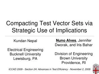
Compacting Test Vector Sets via Strategic Use of Implications Kundan Nepal Electrical Engineering Bucknell University Lewisburg, PA Nuno Alves, Jennifer Dworak, and Iris Bahar Division of Engineering Brown University Providence, RI ICCAD 2009 - Section 2A: Advances in Test Efficiency - November 2, 2009 1
Goal and Motivation • Goal: Reduce the number of test vectors while maintaining the same test coverage • Why important? • Test time is expensive • Smaller feature sizes devices g increased logic amount g increased test data volume • Increased complexity of defects and process variations require more circuit testing
Related techniques • ATPG • Static and dynamic compaction techniques • Design for testability • Built In Self Test (BIST) • Scan chains (with on-chip decompression) • Test Points
Our previous work • Use of logic implication checkers, inserted in hardware, as a means of compacting n-detect test sets • “Using implications for online error detection,” in ITC08 • “Detecting errors using multi-cycle invariance information,” in DATE09
X n1 n5=1 n8=0 X 0 n2 0 X 0 n8 n3 n4 n5 n6 n7 Invariant relationships in circuits 0 0 0 1
n1 n5=1 n8=0 n2 n8 n3 n4 n5 n6 n7 Error detection with implications ERROR n5=1 & n8=1 will generate an error in checker logic
n1 = Stuck@1 fault n5=1 n8=0 n2 n8 n3 n4 n5 n6 n7 Implication Violations Can Detect Errors ERROR Appropriate checker logic can detect multiple errors with a single implication.
Implications for Online Error Detection • Our algorithm automatically identifies implications in circuits • Implication selection can be constrained by hardware overhead or delay • For several circuits, we can detect almost 90% of all errors that propagate to a primary output
Implications for test vector compaction • Why are test vector sets large? • Certain faults in a circuit are hard to detect • A circuit with many hard to detect faults requires lots of test vectors • How can implications help? • Implications may make faults easier to observe, therefore pattern count can be reduced 9
Why Do We Want to Detect Faults Multiple Times? • Faults targeted during test are not perfect models of “real world” defects. • Each “real world” defect may have its own requirements for detection. • However certain observation requirements overlap. • By observing a site multiple times, you have multiple opportunities to meet additional requirements for detecting real defects.
Defects & Faults May Not Match To detect the OR bridge with a test for A s-a-1, B must equal 1. A s-a-1 0/1 0 A 1 S P 0/1 1/1 0/1 A OR B bridge 0/0 F 0/0 Q 1 B 0/0 OR bridge: Observation could be satisfied by observation of A s-a-1 Excitation requires satisfying an additional constraint
Defects & Faults May Not Match To detect the OR bridge with a test for A s-a-1, B must equal 0. A s-a-1 0/1 0 A 1 S P 0/1 1/1 0/1 A OR B bridge 0/0 F 0/0 Q 0 B 1/1 If we observe a site multiple times with different test patterns we increase our chances of fortuitously exciting whatever un-modeled defect may be present.
Implications generate additional fault observations • Circuit rd73 (MCNC91), has 700 faults and 7 inputs • We report the fault observations after all 128 vectors were simulated
Selecting implications for test • So far, • We’ve introduced implications • Shown that implications can make faults easier to detect • Now, • Can we not only use implications for on-line error detection, but also to reduce test vector size?
circuit 15-detect vectors ATPG Run Algorithm Setup • Goal: Find the implications that yield the largest reduction of patterns
Compress implications Create Fault Dictionaries (f×p matrices) Discover implications • Calculate Implications: Using circuit simulation and SAT-based verification, discover all implications in the circuit • Compress Implications: Remove dominated and low quality implications • For each implication, create an individual fault dictionary with the 15-detect vectors circuit Creating Fault Dictionaries ATPG Run 15-detect vectors
Selected implications Implication selection alg. Compress implications Create Fault Dictionaries (f×p matrices) circuit Implication Selection ATPG Run Discover implications • For each fault dictionary, implication selection algorithm determines which vectors may be safely deleted while keeping 15 detects 15-detect vectors • Add the best performing implication to the original circuit and repeat the process
Pattern Fault Original Circuit Selection Algorithm: An Example • 2-Detect patterns: Fault propagate at least twice • Red square indicates a fault that was propagated to a primary output (PO)
Pattern Fault Original Circuit Selection Algorithm: An Example Pattern Fault Circuit with Implication #1 • Circuit with implication has more propagated faults • Pattern 4 is no longer required for 2-detections. With implication #1 only 4 vectors are required.
Pattern Fault Original Circuit Selection Algorithm: An Example Pattern Fault • For each implication, the algorithm continues to calculate the minimum number of 2-detect vectors
Selection Algorithm: An Example Pattern Pattern Fault Fault Original Circuit Circuit with Implication #1 Circuit + 1 Implication • Once we find the best implication, which gives the best 2-detect vector count reduction, we add it to the original circuit • We then restart the process
Selected implications Implication selection alg. Compress implications Create Fault Dictionaries (f×p matrices) circuit Experimental Setting ATPG Run Discover implications • Stuck-at fault model • Benchmarks from ISCAS85 and MCNC91 • ATPG tool: Mentor Graphics FastScan • Synthesis Tool: Mentor Graphics Leonardo Spectrum 15-detect vectors
Online error detection and pattern reduction for different HW overheads The implication checker can have a dual purpose
Conclusions • Logic implications can be used for online error detection and test • Implications optimized to reduce average pattern count: • 8% Reduction (1% HW) • 17% Reduction (5% HW)
Future Work • Create more sophisticated implication selection algorithms • Develop algorithms that optimize implication selection for online error detection and test together • Use of cross-cycle implications
Compacting Test Vector Sets via Strategic Use of Implications Nuno Alves (speaker) - nuno@brown.edu Kundan Nepal - kundan.nepal@bucknell.edu Jennifer Dworak - jennifer_dworak@brown.edu Iris Bahar - iris_bahar@brown.edu
Implications and delay • Circuits with added implications corresponding to 5% HW overhead • TSMC 180nm Model • Preserved Critical path • Delay was increased an average of 2%