Download
1 / 41
420 likes | 637 Vues
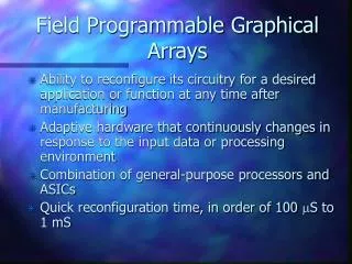
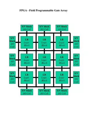
Introduction to Field Programmable Gate Arrays. Lecture 2/3 CERN Accelerator School on Digital Signal Processing Sigtuna, Sweden, 31 May – 9 June 2007 Javier Serrano, CERN AB-CO-HT. Outline. Digital Signal Processing using FPGAs Introduction. Why FPGAs for DSP?

E N D
Introduction to Field Programmable Gate Arrays Lecture 2/3 CERN Accelerator School on Digital Signal Processing Sigtuna, Sweden, 31 May – 9 June 2007 Javier Serrano, CERN AB-CO-HT
Outline • Digital Signal Processing using FPGAs • Introduction. Why FPGAs for DSP? • Fixed point and its subtleties. • Doing arithmetic in hardware. • Distributed Arithmetic (DA). • COordinate Rotation DIgital Computer (CORDIC).
Outline • Digital Signal Processing using FPGAs • Introduction. Why FPGAs for DSP? • Fixed point and its subtleties. • Doing arithmetic in hardware. • Distributed Arithmetic (DA). • COordinate Rotation DIgital Computer (CORDIC).
Why FPGAs for DSP? (1) Reason 1: FPGAs handle high computational workloads FPGA Conventional DSP Device(Von Neumann architecture) Data In Data In Reg1 Reg2 Reg255 Reg0 Reg C0 C1 C2 C255 .... MAC unit Data Out Data Out 256 Loops needed to process samples All 256 MAC operations in 1 clock cycle
FPGAs are ideal for multi-channel DSP designs • Many low sample rate channels can be multiplexed (e.g. TDM) and processed in the FPGA, at a high rate. • Interpolation (using zeros) can also drive sample rates higher. 80MHz Samples ch1 20MHz Samples LPF ch2 LPF LPF ch3 LPF Multi Channel Filter ch4 LPF
× × × × + + + + + + Why FPGAs for DSP? (2) Reason 2: Tremendous Flexibility A Q = (A x B) + (C x D) + (E x F) + (G x H) can be implemented in parallel B C D Q E F G H But is this the only way in the FPGA?
× × × × × × × D Q + + + + + + + + + + + + Customize Architectures to Suit Your Ideal Algorithms Parallel Semi-Parallel Serial D Q Speed Optimized for? Cost FPGAs allow Area (cost) / Performance tradeoffs
Hundreds of Termination Resistors A/D AFE A/D DSP Procs. DDC DDC MACs MACs FPGA DDC DDC Control Control SDRAM SDRAM FPGA D/A DUC DUC DSP Card D/A DUC DUC SDRAM SDRAM Why FPGAs for DSP? (3) Reason 3: Integration simplifies PCBs ASSP SSTL3 Translators Quad TRx PowerPC NetworkCard Quad TRx A/D ASSP A/D Control PL4 3.125 Gbps PowerPC PowerPC MACs, DUCs, DDCs, Logic D/A PowerPC PowerPC D/A Control CORBA
Outline • Digital Signal Processing using FPGAs • Introduction. Why FPGAs for DSP? • Fixed point and its subtleties. • Doing arithmetic in hardware. • Distributed Arithmetic (DA). • COordinate Rotation DIgital Computer (CORDIC).
Fixed point binary numbers Example: 3 integer bits and 5 fractional bits
Fixed point truncation vs. rounding Note that in 2’s complement, truncation is biased while rounding isn’t.
Outline • Digital Signal Processing using FPGAs • Introduction. Why FPGAs for DSP? • Fixed point and its subtleties. • Doing arithmetic in hardware. • Distributed Arithmetic (DA). • COordinate Rotation DIgital Computer (CORDIC).
Add/subtract circuit S = A+B when Control=‘0’ S = A-B when Control=‘1’
Saturation You can’t let the data path become arbitrarily wide. Saturation involves overflow detection and a multiplexer. Useful in accumulators (like the one in the PI controller we use in the lab).
A 4-bit unsigned multiplier using Full Adders and AND gates Of course, you can use embedded multipliers if your chip has them!
Constant coefficient multipliers using ROM For “easy” coefficients, there are smarter ways. E.g. to multiply a number A by 31, left-shift A by 5 places then subtract A.
Division: pencil & paper • Uses add/subtract blocks presented earlier. • MSB produced first: this will usually imply we have to wait for whole operation to finish before feeding result to another block. • Longer combinational delays than in multiplication: an N by N division will always take longer than an N by N multiplication.
Square root • Take a division array, cut it in half (diagonally) and you have square root. Square root is therefore faster than division! • Although with less ripple through, this block suffers from the same problems as the division array. • Alternative approach: first guess with a ROM, then use an iterative algorithm such as Newton-Raphson.
Outline • Digital Signal Processing using FPGAs • Introduction. Why FPGAs for DSP? • Fixed point and its subtleties. • Doing arithmetic in hardware. • Distributed Arithmetic (DA). • COordinate Rotation DIgital Computer (CORDIC).
Distributed Arithmetic (DA) 1/2 Digital filtering is about sums of products: c[n] constant (prerequisite to use DA) x[n] input signal B bits wide Let’s assume: xb[n] is bit number b of x[n] (either 0 or 1) Then: And after some rearrangement of terms: This can be implemented with an N-input LUT
Distributed Arithmetic (DA) 2/2 LUT + Register xB[0] …… x1[0] x0[0] xB[1] …… x1[1] x0[1] y …….... …….... …….... xB[N-1] …… x1[N-1] x0[N-1] 2-1 Generates a result every B clock ticks. Replicating logic one can trade off speed vs. area, to the limit of getting one result per clock tick.
Outline • Digital Signal Processing using FPGAs • Introduction. Why FPGAs for DSP? • Fixed point and its subtleties. • Doing arithmetic in hardware. • Distributed Arithmetic (DA). • COordinate Rotation DIgital Computer (CORDIC).
Vectoring Mode Vector magnitude
Acknowledgements • Many thanks to Jeff Weintraub (Xilinx University Program) and Bob Stewart (University of Strathclyde) for many of these slides.