Download
1 / 37
370 likes | 527 Vues
Fault Tolerance in Field Programmable Gate Arrays. Nehir Sönmez 12/5/2005. LE. LE. LE. LE. LE. LE. LE. LE. LE. LE. LE. LE. FPGA. Tracks. Each logic element outputs one data bit. Interconnect programmable between elements. Interconnect tracks grouped into channels.

E N D
Fault Tolerance in Field Programmable Gate Arrays Nehir Sönmez 12/5/2005
LE LE LE LE LE LE LE LE LE LE LE LE FPGA Tracks • Each logic element outputs one data bit. • Interconnect programmable between elements. • Interconnect tracks grouped into channels. Logic Element
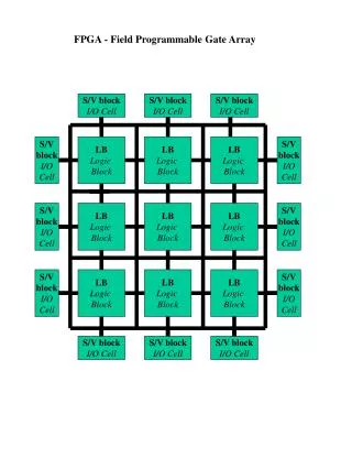
FPGA Architecture • Basic Building Blocks – Programmable (Configurable) Logic Blocks (PLBs) – Input/Output Blocks (IOBs) – Programmable Switch Matrices (PSMs) • Routing Resources: > 50% of die area – Wires – Configuration Interconnect Points (CIPs)
Reconfigurable Hardware Logic Element • Each logic element operates on four one-bit inputs. • Output is one data bit. • Can perform any boolean function of four inputs 2 = 64K functions! A B Out C D A B C D = out 4 2
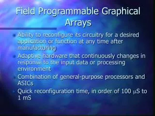
Reconfiguration • Reconfiguration methodology • Static • Partially static (=partial reconfiguration) • Dynamic
RTR = CPU + FPGA • CPU re-programs FPGA • Useful for: • Co-processing • Reducing CPU size and speed • Increasing system performance • Lower system power • Reducing system cost • Enabling Defect / Fault Tolerance • normal system operation involves reconfiguring FPGAs for different functions, -> controlled by a module external to FPGAs ie. an embedded microprocessor with memory to store configurations. • Extend tasks of this processor to also control the test, diagnosis, and fault-tolerance functions
Why Fault Tolerance in FPGAs? • Decreasing trace sizes increase faults • Increasing speed increases faults • Inherently reconfigurable, should be perfect for FT • Graceful degradation would be nice
Early Efforts at Reconfiguration • Grew out of yield enhancement • PROM technology • Reconfiguration techniques used “spare” CLBs to improve yield 50% • Did not address fault detection, location, or any runtime faults • Toward Runtime Reconfiguring: Emmert and Bhatia • Used “replacement CLB chains” to reassign CLBs to avoid faulty CLBs • Broke problem into a series of incremental (and easier) reroutings • Did not address interconnect faults • Not runtime yet, allowed use of damaged components
First Runtime Reconfiguring • Hanchek and Dutt • Created first runtime solution • Changed interconnect rules to simplify • Guaranteed rerouting in linear time • Only supported one fault per row • Lach, Mangione-Smith, Potkonjak • Primary problem: computing power • Use tiling to pre-compute configurations • Configurations each avoid different CLBs • At runtime choose one, based on the fault location • Like TMR
Tile Reconfiguration Issues • Solutions probably have different timing • Finding worse case is combinatorial • Must assume worse case during design • Adjusting tile size changes redundancy • Applicable to interconnect faults in tiles • Does not address interconnect faults at tile boundaries, does not detect, locate
Runtime Reconfiguring, Take III • Mahapatra and Dutt • Runtime router based on static “covering chains” created during design • Guaranteed solution if enough working CLBs exist • Still no solution to detection/location
What about Fault Detection? • Grew out of yield enhancement • Originally BIST used to verify FPGAs • Products added BIST to POST • Products use BIST to self-diagnose and provide more information to users
Runtime Fault Detection • Shnidman, Mangione-Smith, Potkonjak • Proposed running BIST simultaneously with primary operation • Created a specification for an FPGA that would allow “Fault Scanning” • Reserves 2 CLBs columns
Fault Scanning Issues • Hardware redundancy: 2/Ncolumns • Much lower than TMR/NMR • Test shuttles back-and-forth • Errors not detected immediately • Detection latency is linear with Ncolumns • Doubled size of state for CLBs and interconnect matrices • Only works on bus-based interconnect
What would runtime FT look like? • Use inherent reconfigurable nature • Lower overhead than TMR/NMR • Involve runtime relocation and rerouting • Latency based on scanning time • Graceful degradation • Work on existing hardware • CLB and interconnect faults • Handle SEUs as well as permanent faults
Runtime FT in FPGAs • Abramovici, Emmert, Hamilton, Skaggs, Stroud, Verma, Wijesuriya • Meets all above criteria • Implemented example on existing HW • Added extensive use of controller • First time that FT is programmable • Algorithm (not design) for HW FT! • Approach: 1) Isolate defects 2) Program device around defects
Roving Self-Test Areas • Reserve 2 CLBs in each direction • Hardware redundancy: • 1-(N-2)2/N2 • The overhead decreases with N. • For example, for N=20, OV is 19%, but for N=40, OV is only 10%. • STARs are “invisible” to working CLBs • “Through” interconnect unused by STAR • Tricky process for moving functionality • Must stop the clock during CLB move • Filled with BISTERs
Test and Reconfiguration Controller(TREC) • TREC accesses an FPGA using its boundary-scan mechanism (access is transparent to the normal function of the chip) • Accesses BISTERs, uses TCK (test clock) • TREC uses RunTimeReconf. to rove the STARs across the chip and to reconfigure them for different test and diagnosis operations. TREC initiates the BISTERs and analyzes their test results. TREC has the capability to stop the system operation for short intervals for safe relocation • faults detected, TREC starts the diagnosis process. TREC also keeps track of the status of FPGA resources, so that defective hardware is avoided when part of the working area is relocated in the previous STAR. • If area contains a Partially Usable Block, TREC determines if the function of the PLB (to be moved in the PUB location) matches the functions that the PUB can correctly perform. • If a PLB or a wire may not be used, then TREC determines configuration changes to the working area so that the defective resources are bypassed and replaced by fault-free ones.
What’s a BISTER? • 6 CLBs that test each other • Tiled into STARs • Allows simultaneous testing of CLBs
BISTER • STAR: several disjoint tiles, PLBs in each tile form a BISTER. • A BISTER contains a Test Pattern Generator applying test patterns to two identically configured blocks under test(BUTs) • outputs are compared by an Output Response Analyser. The ORA latches and reports mismatches as test failures. • Start/Reset andPass/Fail: two interface signals via boundary-scan access mechanism. • Start/Reset is used toinitiate the BIST sequence and to reset the TPG and ORA. The test result Pass/Fail is captured in a FF which is part of ascan register. • two more inputs: TCK and a control input forscanning out the Pass/Fail results from each BISTER. • Initial BISTER configuration checks the proper operationof the scan register, inducing mismatches by comparing BUTs with different configurations. • This protectsagainst the case of all ORA FFs being stuck at the “Pass” value.
The PLB • typical structure of a PLB, composed of a memory module, a register, and a combinational outputmodule. • The memory block can implement combinationallook-up tables (LUTs) or RAM. • PLBs also contain special-purpose logic for arithmetic functions (counters, adders, multipliers, etc.) The register can be configured as flip-flops or latches with programmable clock-enable, preset/clear, and data selector functions. TheBUTs are repeatedly configured to be exhaustively tested in every mode of operation. • The configuration of the TPG also changes when a new BUT configuration requires different patterns.
Functionality and Size of ORA&TPG • To test combinational functions implemented by a LUT with n inputs, the TPG is a counter that generates all possible 2n vectors • to test the RAM, the TPG is a state machine generating standard RAM sequences, which are known to be exhaustive for the fault models specific to RAMs, such as pattern-sensitive faults. • ORA needs to be reconfigured when the new mode of operation of BUT involves a different number of outputs. • Since a BISTER provides complete testing only for its BUTs, we have to reconfigure every BISTER several timesso that every PLB will be a BUT in at least one configuration. • Test time for a BISTER (total roving time) is mostly reconfiguration time (much larger than the BIST time). • to reduce the latency of the procedure,try to minimize the number of PLBs in a BISTER. • The number of PLBs for an ORA and for a TPG depend on the target PLB architecture. Usually the number of outputs in a PLB is smaller than its number of inputs. Since a TPG must provide exhaustive patterns for BUTs, more than one PLB is needed to construct the TPG. • This example: a TPG needs three PLBs and an ORA only one.
BIST:built-in self test • six floor plans of a BISTER tile, T: TPG, B: BUT, O: ORA cell • A BISTER tile may contain additional spare PLBs to help reduce the use of global horizontal routing resources by the internal BISTER connections. • We arrange the number of spare PLBs so that a tile will have an even number of PLBs, symmetrically distributed between the two columns of the V-STAR. • The goal: systematically rotate the functions of the PLBs, so that eventually every PLB in the tile is completely tested twice, each time being compared with a different BUT.
Claims • Claim 1: Any single faulty PLB is guaranteed to be detected in at least two BISTER configurations. • Proof: The faulty PLB is a BUT in two BISTER configurations, where its exhaustive inputs patterns are produced by a fault-free TPG, and its outputs are compared with a fault-free BUT by a fault-free ORA. Hence no fault (single or multiple) detected in the BUT can escape detection in these two configurations. • Claim 2: Except for a few pathological cases, any pair of faulty PLBs is guaranteed to be detected in at least one BISTERconfiguration. • Claim 3: any combination of faulty PLBs is detected in at least one BISTER configuration. If the number of PLBs in a STAR is not a multiple of the number of PLBs in a tile, then the “leftover” PLBs that could not make up a BISTER will be grouped with some of the PLBs already tested in the adjacent tile, so that every PLB in the STAR will eventually be part of a BISTER.
PLB Diagnosis • When failures are detected in the STAR, additional configurations are downloaded to locate the faulty PLB(s). Separate Pass/Fail results from independent BISTERs provide initial sets of suspects. • consider all PLBs in a failing BISTER tile as suspects. • create new BISTERs that divide the suspected PLBs into subsets that are separately tested. • repeat the procedure until all faulty PLBs are identified
PLB Diagnosis • Ex. V-STAR has a failing BISTER with six suspected PLBs. • split in two sets - {A,B} and {C,D,E,F} - included in separate BISTERs, other PLBs were shown to be fault-free. • Next assume the upper BISTER passes all its tests, lower one fails. • split remaining in two sets - {C,D} and {E,F} - include in separate BISTERs. • Next assume the E and F are found to be fault-free. • now the remaining suspects - C and D - reside in the same row and may not be included in separate BISTERs. To complete the diagnosis, we reconfigure to bring H-STAR over the row with C and D, which now may be tested in separate horizontal BISTERs. • eventually all faulty PLBs in V-STAR precisely located, along with their failing modes of operation. • TREC uses these data to assess whether the faulty PLBs may be used as PUBs in subsequent system operation.
BISTER for the Interconnect • The programmable interconnect network consists of wire segments of different length that can be connected via configuration interconnect points (CIPs). • Similar approach, to detect any possible short in the fault model • two BUTs are replaced by two groups of wires under test (WUTs). A WUT may be composed of several wire segments connected by closed CIPs. To check local interconnect, WUTs may also go through PLBs configured as identity functions (passing their inputs directly to their outputs). • TPG applies all possible 2n test patterns to every group of n WUTs. • generating exhaustive patterns with a n-bit counter requires less PLBs than generating the two n-bit walking patterns(contained in the exhaustive set).
The Roving Mechanism • Once a STAR has been tested, the STAR roving process continues by relocating the working area adjacent to the STAR over the current STAR position, and by reconfiguring the just-released working area as a new STAR. • Initial state:A, D, E, and F are working PLBs, B and C are part of V-STAR. • Assume all test activity has stopped without detecting any faults, while the normal operation continues. TREC performs the following operations: • Configure B and C with the functions of D and E; • Stop the system clock; • If necessary, copy the state of D and E into B and C; • Reconfigure to maintain the correct interconnections among working PLBs; • Restart the system clock; • Configure the BISTER tiles in the new STAR and restart testing.
“gracefuldegradation” • In most conventional FT methods, faultsare detected within the working part of the system, and theymust be located and bypassed as fast as possible to restart thenormal operation as soon as possible. • roving STARs:no severe real-time constraints on fault diagnosis & reconfiguration • since the normal system operation is continuing in the workingarea, we can allow much more time for accurate diagnosisor for computing fault-bypassing reconfigurations, comparedwith an approach where normal operation is interrupted fordiagnosis and reconfiguration. • the spare resources are always present in theneighborhood of the located fault. Thus fault reconfigurationpaths may be much shorter than in other methods, and we cantolerate fault clusters that the static FT methods cannot.
PUB: Partially Usable Block • Another novel FT concept is the PUB, that allows faultyPLBs to be safely used as a spares whenever possible, thusincreasing the effective spare capacity and enabling anextended mission life-span. • This idea may be extended toeven a lower level, such as reusing only a subset of the FFs ora subset of the outputs of a faulty PLB. • The testingstrategy guarantees that the PUB works correctly in everynon-failing mode of operation, because it has passed anexhaustive test in every such mode. • Ex. a PLB with faulty flip-flops may still be safely used for combinationallogic, or a PLB with a faulty multiplier may still be safelyused as an adder. • the reuse ofdefective hardware resources: a more gracefuldegradation, compared to “throwing away” the defectiveblocks.
Tolerating an Unusable Faulty PLB • assume C is faulty PLB • If the LUT in C is fault-free, then the combinational function of E may be still be transferred to C, (the PUB C is as good as a fault-free PLB for the function of E.) • assume C has a faulty LUT, so it may not replace E. Although V-STAR will be placed in the columns of D and E, we will use D as a working PLB replacement for E and exclude it from the STAR. After values are transferred from D to B, D may be configured with the function of E • Although E is now part of the STAR, it cannot be part of any BISTER tile. Because of the faulty PLB, we lost one of the spare cells in this row, and from now on the PLBs in this row can no longer be tested by V-STAR. • But here we can bring H-STAR to test these PLBs
Conclusions • An on-line FPGA testing, diagnosis, and fault-tolerance, applicableto any FPGA supporting Real Time Reconfiguration. • Self-testing goes on without disturbing the normal systemactivity in the rest of the chip. • The roving of the STARs periodically brings every section of the device under test. guarantees complete testing of both PLBs and interconnect,does not require any part of the chip to be fault-free. • A STAR consists of several independent BISTERs, which concurrently testdisjoint tiles of the STAR. • A BISTER is repeatedly configured using a rotating strategy so that every PLB in its tile is completely tested in every mode of operation, and practically any combination of faulty PLBs is guaranteed to be detected.
Conclusions • All test-related activities are done without disturbing the normal system operation. • a dynamic FT method, whereboth spare interconnect and spare PLB resources needed tobypass a fault are allocated only after the fault has beendetected and diagnosed, • the spare resources are alwayspresent in the neighborhood of the located fault. • In addition to reporting a faulty PLB, also identify its failing internal module or its failing modeof operation. provides the defective PLB to be used in the system logic, provided that itsintended operation is not affected by the identified faults. • This results in a more graceful degradation and longer missionlife.