Production Drawings
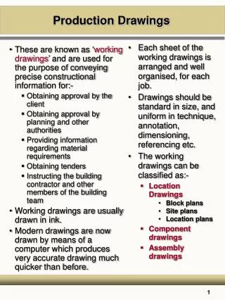
These are known as ‘ working drawings ’ and are used for the purpose of conveying precise constructional information for:- Obtaining approval by the client Obtaining approval by planning and other authorities Providing information regarding material requirements Obtaining tenders

Production Drawings
E N D
Presentation Transcript
These are known as ‘working drawings’ and are used for the purpose of conveying precise constructional information for:- Obtaining approval by the client Obtaining approval by planning and other authorities Providing information regarding material requirements Obtaining tenders Instructing the building contractor and other members of the building team Working drawings are usually drawn in ink. Modern drawings are now drawn by means of a computer which produces very accurate drawing much quicker than before. Each sheet of the working drawings is arranged and well organised, for each job. Drawings should be standard in size, and uniform in technique, annotation, dimensioning, referencing etc. The working drawings can be classified as:- Location Drawings Block plans Site plans Location plans Component drawings Assembly drawings Production Drawings
Block Plans These are used to identify the site in relation to the surrounding area
Block Plans • The scale is usually 1:2500, 1:250 and is too small to allow much more than an outline of the site and boundaries, road layouts and the other buildings in the near vicinity. • The orientation of the site is always shown with a suitable logo depicting north. • The actual site should be outlined in red. • It is not likely that dimensions would be added to these drawings. • Plans of this sort are usually based on the Ordnance Survey sheet for the area however, if such a source is used, permission should be obtained for its reproduction.
Site Plans These are used to show the position of the proposed building on the site, together with information on proposed road, drainage, and service layouts, and other site information such as levels.
Site Plans • The orientation of the site should be shown. • Scales of 1:500, 1:200 are often used. • The information on this drawing is used by both the design team and the contractors. • The drainage layout should be used in conjunction with the drainage schedule, which will give details of manhole construction, cover and invert levels, and other relevant information.
Location Plans These are used to show the size and position of the various rooms within the buildings and to position the principle elements and components.
Elevations • Elevations consist of a series of views of a building or object. • The views are front elevation, side elevation and rear elevation. • They are drawn to a scale of 1:200, 1:100, 1: 50 depending upon the detail required. • Elevations to scale of 1:200 will not show as much detail as elevations to a scale of 1:50. • Elevations show the building as a finished building from all directions. • These drawings have a limited amount of information and dimensions on them, this must be obtained from other drawings.
Plans • These are cross sectional views of a building sowing the position and size of all rooms, toilets, bathrooms, entrances, the position of windows etc. • It also shows the circulation routes and overall character of the building. • These drawings are drawn to a scale of 1:200, 1:100 and 1:50 and usually match the elevations in size. • Because of this they are still too small to show much information or dimensions.
Sections • The sectional view of a building will show details which otherwise would not be seen on the plans and elevations. • These drawings can show a cross sectional view or a longitudinal view of the building and can display either a full cross section or a part cross section. • A full cross section will show the full height of the building and its respective floor and ceiling levels. • Depending on the scale chosen, information will be restricted to that which could not be found in other drawings.
Component drawings • These are some times called range drawings. These show the basic sizes of standard components such as doors, windows and kitchen fitments. • The scales most commonly used are 1:100, 1: 50, 1: 20. • The drawing below shows a range of windows. These can be obtained from any manufactures catalogue or from the working drawings. • All windows are referenced i.e. W1, W2, W3 etc • These refer to the working drawings and the window schedule.
Detail drawings • These show all the relevant information that is required to manufacture various components such as doors and windows etc • These drawings will include every detail required to make the product. • The information from these details is used to manufacture various components. • These drawings are usually produced by the architect and are produced in scales ranging from 1:1, 1: 5, or 1:10.
Assembly drawings • These drawings show in detail the junction between the various elements and components of a building • These drawings are very important to the builder. They show in detail how the architect requires the construction to be constructed and what materials should be used. • The scales usually used for these drawings are 1:20, 1:10, and 1:5 and should be fully dimensioned and annotated.