Download
1 / 48
480 likes | 634 Vues
Turbulence Radar Flight Data Analysis. May 23, 2001. Phil Schaffner Turbulence Radar Principal Investigator Sensors Research Branch NASA Langley Research Center Hampton, VA 23681-2199 (757) 864-1809 E-mail: P.R.Schaffner@LaRC.NASA.gov. Presentation Outline. Introduction

E N D
Turbulence Radar Flight Data Analysis May 23, 2001 Phil Schaffner Turbulence Radar Principal Investigator Sensors Research Branch NASA Langley Research Center Hampton, VA 23681-2199 (757) 864-1809 E-mail: P.R.Schaffner@LaRC.NASA.gov NASA Langley Research Center
Presentation Outline • Introduction • Flight Configuration • Flight Operations Summary • Event Summary • Data Report and Analyses by Flight • Flight Test Summary • CY01 Flight Plans NASA Langley Research Center
Aviation Safety Program Organization Aviation Safety Program Office 1.0 Mike Lewis Government/IndustryProgram Leadership Team Technical Integration 1.1 Vince Schultz (LaRC) Level 1- Program Single Aircraft Accident Prevention 2.3 John White (LaRC) Weather Accident Prevention 2.4 Shari Nadell (GRC) System-Wide Accident Prevention 2.2 Dave Foyle (ARC) Accident Mitigation 2.5 Doug Rohn (GRC) Synthetic Vision 2.6 Dan Baize (LaRC) Aviation System Monitoring & Modeling 2.1 Yuri Gawdiak (ARC) Level 2- Projects Aviation Weather Information (AWIN) 2.4.1 Paul Stough (LaRC) Weather Information Communication (WINCOMM) 2.4.2 Gus Martzaklis (GRC) Turbulence Detection & Mitigation (TDAM) 2.4.3 Rod Bogue (DFRC) Aircraft Icing (Base Program) Level 3- Elements NASA Langley Research Center
Turbulence Detection Level 4 Sub-element • Sensor Performance Assessment • Sensor Development • Algorithm Development • Demonstration & Verification NASA Langley Research Center
Objectives WxAP Objective #3 Provide commercial aircraft sensor with 90% probability of detection of severe Convective and Clear Air Turbulence thirty seconds to two minutes before encounter. WxAP Milestone #2 Flight demonstrate certifiable forward-looking on-board turbulence warning system with Type-I and Type-II error probability commensurate with airborne wind shear technology. [TRL/IRL of 7/4] Goal for NASA/FAA/Industry Advance warning of 30 sec. with POD 80% for phenomena with reflectivity 15 dBz. NASA Langley Research Center
Flight Operations Summary • Weather Support • Forecasting and pre-flight recommendations • 2-, 1-, and day of operation forecasts • Pilot briefings • Onboard tactical recommendations • Real-time observations • In Situ • Data Collection • Real-time engineering displays • Post-flight processing • Turbulence Radar • Data collection • Real-time engineering displays • Aircraft response algorithms NASA Langley Research Center
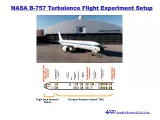
1.75” Reflectivity Velocity Flat Panel Display 15.75” sDn Spectral Width WXI-711 Indicator & CTRL 10.50” 1.75” 1.75” Record Computer Monitor WX MAP TRFC WX/TRB 7.00” Rec. Comp. Keyboard Proc. Comp. Keyboard IRIG Time Readout GAIN ANT Radar Configuration/Control (RS-232) A/C State Parameters (8x(ARINC 429)) RADAR Processing Computer RADAR Recording Computer Radar State Parameters (ARINC 429) 7.00” Radar I/Q (Fiber Channel) 3.50” PALLET PWR DIST 3.50” POWER SUB PANEL Radar Data Collection Design Layout As Built • CY’00 Radar Flight Test Objectives • Collect airborne radar signatures of turbulence (along with aircraft response) to enable characterization and algorithm development/refinement. • Assess the performance of the latest-generation turbulence detection and hazard estimation algorithms. Alternating Antenna Sweeps: Std. WX/WS Research Mode Antenna Recorded Information R/T Unit A/C State Parameters (4x(ARINC 429)) NASA Langley Research Center
An End-to-End Turbulence Radar System Radar signal processing algorithm Radar Hardware Radar turbulence hazard tables Significant Gust Turbulence Alert criteria Display/Alert NASA Langley Research Center
Baseline Algorithm Methodology • Includes time-domain interference-rejection filter • Frequency/Doppler-velocity domain spectral width estimation • Optional averaging over range and/or azimuth • Estimates turbulence correlation length • Thresholding using CFAR (constant false alarm rate) threshold calculated from the spectra • Estimates point variance from spectral width and bin-to-bin variance of average velocity • Uses Hazard Tables to predict RMS accelerations from point variance NASA Langley Research Center
NCAR Algorithm Methodology • The NCAR Efficient Spectral Processing Algorithm (NESPA) is a multi-stage approach to finding high-quality Doppler moments in real-time. • Data quality is improved by averaging the spectra over multiple azimuths and ranges. • Hazard metrics are produced by scaling the second moment estimates using tables and combining the results from three elevation angles. • Confidence measures based on many different indicators (e.g. SNR, continuity, etc.) of data quality are used in the multi-stage processing and are also used in the calculation of the hazard metrics. NASA Langley Research Center
Radar Hazard Tables • Relate radar estimates of spectral width or point variance to predicted variance of aircraft accelerations • Key part of system to go from radar data processing algorithm output to aircraft effects NASA Langley Research Center
Light Moderate Severe Extreme less than 0.2 g 0.2 to 0.3 g greater than 0.3 to 0.6 g over 0.6 g Hazard Levels: RMS Vertical Acceleration NASA Langley Research Center
Proposed Alert Criteria Goal: Advance warning of 30 sec. with POD 80% for phenomena with reflectivity 15 dBz. Alerts Based on Radar Observables No Alert May Alert Must Alert Predicted Hazard n0.2g 0.2g n0.3g n 0.3g NASA Langley Research Center
3.0 2.5 18 NASA Events 2.0 10 NTSB Accidents 6 FOQA Incidents 1.5 1.0 0.5 0.0 0.0 0.1 0.2 0.3 0.4 0.5 0.6 0.7 0.8 0.9 1.0 Correlation of Peak Load With Peak RMS Load ( 5 sec. window) y = 7.6084e-2 + 2.6193x R^2 = 0.958 DATA SOURCES Peak | n | g's 191 - 06 moderate severe extreme Peak RMS n g's RLB Based on Measurements for 34 Turbulence Encounter Cases NASA Langley Research Center
Flight Test Summary • Checkout/ferry flights (154, 155, 169) • 3 Data flights • 181: 3 to 4 very low reflectivity encounters with light turbulence • 190 & 191: low reflectivity encounters with light to severe turbulence • 18 in situ events identified from data flights • 7 events selected for detailed radar analysis NASA Langley Research Center
18 Event Summary Table NASA Langley Research Center
7 Event Summary Table NASA Langley Research Center
Flight/Day Weather Primary Region of Interest Peak Storm Tops Cell Movement (from) Fl- 181 16 Nov 2000 Broad Area of Rain with Embedded Convective Cells Southern Mississippi & Louisiana 30,000 feet WSW at 45 kts Fl -190 13 Dec 2000 Broad Area of Rain and Convective Cells with Embedded Thunderstorms Northeast Louisiana 43,000 feet SW at 65 kts Fl -191 14 Dec 2000 Narrow Line of Convective Cells/Thunderstorms Florida Panhandle & South Georgia 40,000 feet SW at 40 kts Weather Summary NASA Langley Research Center
Flight 190 Path NASA Langley Research Center
Flight 190 Weather NASA Langley Research Center
Flight 190 Satellite Weather NASA Langley Research Center
Flight 190 Event 06 Normal Loads 68080 sec. 68170 sec. NASA Langley Research Center
Reflectivity (dBZ) Event 190-06 18:45:21 or 67521 seconds NASA Langley Research Center
g-Loading (rms g) Event 190-06 18:55:30 or 68130 seconds NASA Langley Research Center
g-Loading (rms g) Event 190-06 18:56:05 or 68165 seconds NASA Langley Research Center
Summary - Case 190-06 • Little reflectivity within scan range • In situ peak rms g ~ 0.33 at 68170 seconds • Missed prediction of in situ peak • Detection of ~0.35 g 5 km (20 seconds) ahead at 68177 seconds where in situ shows ~0.25 • Many areas >0.3 off track NASA Langley Research Center
Flight 191 Weather NASA Langley Research Center
Flight 191 Weather NASA Langley Research Center
191 Path Flight NASA Langley Research Center
Flight 191 Event 03 Normal Loads 66470 NASA Langley Research Center
g-Loading (rms g) Event 191-03 18:26:54 or 66414 seconds NASA Langley Research Center
Reflectivity (dBZ) Event 191-03 18:27:11 or 66431 seconds NASA Langley Research Center
g-Loading (rms g) Event 191-03 18:27:09 or 66429 seconds NASA Langley Research Center
Summary - Event 191-03 • Good reflectivity on port side near path, low reflectivity along path at beginning of run • In situ peak rms g ~ 0.33 at 66470 seconds • Predictions of > 0.32 g along path at 66429 9.5 km (44 seconds) ahead • Multiple hits on successive scans down to ~ 5 km NASA Langley Research Center
Flight 191 Event 06 Normal Loads 67458 sec. NASA Langley Research Center
g-Loading (rms g) Event 191- 06 18:43:22 or 67402 seconds NASA Langley Research Center
g-Loading (rms g) Event 191- 06 18:43:46 or 67426 seconds NASA Langley Research Center
Summary - Event 191-06 • Two major “blobs” of reflectivity 25- 40 dBZ • In situ peak rms g ~ 0.43 at 67458 seconds • Prediction of ~ 0.4 g at 16km (63 seconds) ahead at 67402 seconds • Multiple detections until 67450 seconds NASA Langley Research Center
Type I and Type II Errors • I: Missed Detections/Alerts • II: False Detections/Nuisance Alerts • Insufficient Data to Predict Performance • Performance Predictions Will Require Modeling and Analysis • Unlikely to Acquire Sufficient Experimental Data to Allow Statistical Analysis NASA Langley Research Center
In Situ Radar Low dBZ Bumps 5 4 3 Nulls 3 3 1 Turbulence Radar Results Summary Combined Event Based A’Posteriori Scoring for 7 Radar Events NASA Langley Research Center
Conclusions • Use and method of averaging/filtering will be a key factor in detection and reduction of false alarms • Lack of averaging may cause over-alerting • Averaging can reduce peak load estimates • In Situ truth not available for large part of data • Validated models would enable more thorough algorithm evaluation • Modeling/simulation will support error analysis • Lidar can provide comparison data NASA Langley Research Center
CY01 Flight Objectives • S/W and H/W upgrades • Flight objectives • 40 events 0.2 g or better • Vary radar pulse configuration • Weather variety • Sufficient reflectivity for radar detection • Record I & Q and aircraft data • Test detection algorithms in real time • Research turbulence display for NASA pilots NASA Langley Research Center