Reflection
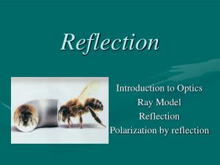
Reflection. Introduction to Optics Ray Model Reflection Polarization by reflection. Reading Question. What is specular reflection?. 1. The image of a specimen. 2. A reflection that separates different colors. 3. Reflection by a flat smooth object.

Reflection
E N D
Presentation Transcript
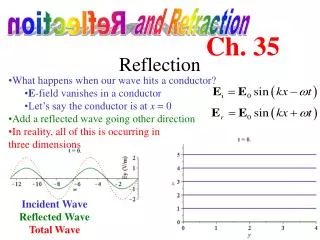
Reflection Introduction to Optics Ray Model Reflection Polarization by reflection
Reading Question What is specular reflection? 1. The image of a specimen. 2. A reflection that separates different colors. 3. Reflection by a flat smooth object. 4. When the image is virtual and special. 5. This topic is not covered in Chapter 23.
Reading Question What is specular reflection? 1. The image of a specimen. 2. A reflection that separates different colors. 3. Reflection by a flat smooth object. 4. When the image is virtual and special. 5. This topic is not covered in Chapter 23.
Reading Question A paraxial ray 1. moves in a parabolic path. 2. is a ray that has been reflected from parabolic mirror. 3. is a ray that moves nearly parallel to the optical axis. 4. is a ray that moves exactly parallel to the optical axis.
Reading Question A paraxial ray 1. moves in a parabolic path. 2. is a ray that has been reflected from parabolic mirror. 3. is a ray that moves nearly parallel to the optical axis. 4. is a ray that moves exactly parallel to the optical axis.
Optics Geometric Optics Physical Optics Reflection
Reflection Refraction Reflection and Refraction what is this? refraction refraction reflection
Rays • Rays are not real but a model to help us understand the nature of light when the objects are large compared to the wavelength.
Objects • Objects are either self-luminous or reflective.
Pin-hole Camera • Camera
Reflection • Ray model to find image.
Reflection • Your image in a mirror
mirror paper N Reflection • On the table you will find a light box and a mirror. Take a clean sheet of paper and place the mirror near the center with the reflective face toward you. Take a pencil and draw a line along the mirror face. Remove the mirror and use a protractor to draw a line perpendicular to the mirror face. Label the line N for normal. Now place the mirror back along the line with the perpendicular line in the center of the mirror.
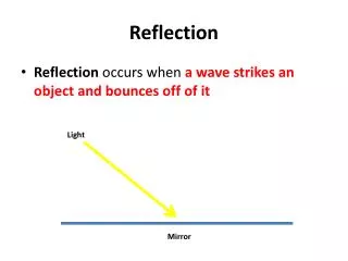
Reflection • Get the light box and turn it on. On the side you will find a sliding window. Slide the window until you have one light beam coming from the light box. Place the light box on the table so that the beam strikes the mirror where the perpendicular line intersects the mirror face. You should see the incident beam and the reflected beam. • Change the angle the light beam makes with the mirror normal and observe the reflected beam.
mirror paper N Reflection • Place the light box so that the beam makes an angle of about 300 to the normal. Trace the incident beam from the light box to the mirror and the reflected beam from the mirror to the edge of the paper. Measure the incident angle and the reflected angle. The angles are measured from the normal. What do you notice about these two angles?
the angle of incidence q1 equals the angle of reflection q1’ the subscript 1 lets you know it is for side 1 Reflection • Write a general equation or relationship between the angle of incident and the angle of reflection. Side 1 Side 2
mirror paper N Reflection • Next we will see how to locate the image of an object in front of a mirror. Get a clean sheet of paper and again place the mirror in the center. Draw a line along the face of the mirror and draw a perpendicular line. Hold a pencil 5 cm in front of the mirror and to the right of the normal as shown. image pencil
image location mirror line eye N eye Reflection • Complete the light path by drawing a line from the pencil to the point where the light beam intersects the mirror. Remove the mirror and continue the two lines until they meet behind the mirror. The point where they meet is the image location. What would happen if you picked a third position and constructed the line? Try it.
Reflection • Measure the perpendicular distance from the mirror to the object and the distance from the mirror to the image point. • How do these two distances compare? • Below is a drawing of a ball in front of a mirror. We will use light beams from the object (ball) to find the image point. Light reflected from the ball propagates out in all directions. I have constructed one such light beam. Now you pick an arbitrary direction for a light beam that reflect off the mirror. Draw the beam and construct a normal to the mirror where the beam strikes the mirror. Draw the beam reflected from the mirror. The image is somewhere along this line. Extend the beam (line) behind the mirror. To find the image on this line consider another beam of light from the ball that reflects off the mirror. Where the two lines meet behind the mirror is where the image is located.
image along this line mirror ball mirror qi qi ball mirror N qi qi ball N Reflection • Construction of a light beam. • Construction of reflected light beam. • Construction of backward projection.
image object mirror Reflection • This is how you find the image. Can you find a general rule for the location of an image for a object in front of a mirror? Discuss this in your group. Write the rule. The image is on a perpendicular line passing through the object and an equal distance behind the mirror.
mirror mirror light box Reflection • Now let’s look at two mirrors that form a corner. Get two mirrors and form a 900 corner with them. Take the light box and position it on the corner mirrors so that the beam reflects off both mirrors.
Reflection • What do you notice about the relationship between the incident beam and the reflected beam? Discuss this in your group. • Does this relationship hold for different incident angles? • Use the same technique as before to find the reflected beam from the two mirrors. Compare the incident beam to the reflected beam. Does the same rule apply as before? They are parallel. Yes.
Reflection • Your rule should be that the incident beam and the reflected beam are parallel. Can you prove this?
Reflection using RAYTRACE • Open the program RAYTRACE that you will find the icon on the desktop. After double clicking to open the program you will have to click again on Run RAYTRACE in the lower right corner of the Title window and then click Go from the Start window. You should see the workspace window. First we will display Grid points. Under Options select Show from the Grid menu to see the grid on the workspace. Next we will select Snap to grid to make it easy to create elements. Under Options again select Grid >Snap to grid from the menu. The cursor should be in Select mode and have the shape of a box with tick marks on the four sides. The tick marks tell you it is in Grid snap mode.
Reflection using RAY program • Next we will create a vertical flat mirror. Under the Create menu select Element > Surface. To create the mirror you move the curser to the start of the mirror and click, then move to the other end of the mirror and click again. You right click and select Finish to complete the mirror. Draw a vertical mirror in the center of the workspace (from left to right) that almost fills the screen from top to bottom. You can delete the mirror and start again by selecting the mirror and pressing the Delete key.
Reflection using RAY program • Now we want to create an object. To do this we will use the Tape measure. Again under the Create menu select Tape measure. To the leaf of the mirror about 16 grid spaces away click once for the bottom of the object and then move 5 grid spaces up and click for the other end of the object. Your object should be 100 units tall. • Next we will create a number of rays so that we can find the image. First we want to change the ray defaults. You can do things like show normal, change color of ray, and show forward projection. For now, we just want to show normal. Under the Defaults menu select Ray setting. Select the Fertility tab and click the Show normal box. This option will now draw a normal to the surface for each reflection.
Reflection using RAY program • Now we will find the position of the top of the image using reflected rays. Select Ray from the Create menu. The cursor should change to Start for the start of the ray. Move the cursor to the top of the object and click. The cursor should change to End. Now move the cursor so that the ray will reflect from the mirror and click. You should see a rubber band stretch as you move the cursor around. Right click and select Finish. The ray should now show a reflection from the mirror. The ray must past through the mirror to show a reflection. Draw a second ray from the top of the object and intersecting the mirror at a different position than the first ray. If we project the reflected rays backward, where the two projections cross is the position of the top of the image. We will use the tape measure to draw a backward projection. First turn off the Snap to grid option by going to the Options menu and selecting Grid > Snap to grid or typing S. Typing S will toggle the Snap to grid on and off. Under Create select Tape measure and move the cursor to some point on one of the reflected rays near the end and click. The cursor should change from Start to End. Now move the cursor so that the tape measure is parallel and covers the reflected ray. Stretch the tape measure as far behind the mirror as possible and click. Do the same for the second reflected ray. Where the two backward projections cross is the top of the image. Repeat this process and find the bottom of the image. Finally we will use the Tape measure to draw the image. Draw a Tape measure from the top image position to the bottom. How does the size of your image compare with the size of the object?
Reflection using RAY program • How does the size of your image compare with the size of the object? Object size __________ Image size __________ • What about the image distance from the mirror. Use the Tape measure and find the distance from the object to the mirror and the distance from the image to the mirror. How do they compare? Object distance __________ Image distance __________
Reflection using RAY program • What about the corner reflector? Select New to clear the workspace and start a new project. Make sure the Show grid and Snap to grid options are selected. Recall how the cursor should look when the Snap to grid is on? Typing S will toggle the Snap to grid option. Using Create > Element > Surface create a corner reflector. Both mirrors can be created in one operation. The first mirror should be horizontal and start from the left-hand side of the workspace in the center from top to bottom, stopping in the center. The second mirror should be vertical and start at the end of the first mirror and end at the bottom of the workspace. You can do this by selecting Create > Element > Surface and move the cursor to the left-hand side of the workspace and click, move the cursor to the center and click, move the cursor to the bottom and click, then right click and select Finish. This is shown below.
Reflection using RAY program • Next create a ray starting in the lower left corner of the workspace and make sure it will reflect off both mirrors. Don’t forget to finish the ray you right click and select Finish. • What do you notice about the double reflected ray compared to the incident ray? • Is this always true? Select the incident ray by clicking on the ray. If you click on the ray end where it intersects the mirror you can drag the intersection up and down the mirror. The cursor should change to drag mode. Move the intersection and observe the double reflected ray and the incident ray. Are they always parallel?
Reflection using RAY program • Now we will find the images from a corner mirror. How many are there? Lets find out. To get rid of the rays select Clear > Rays. Now we will create six ray coming from a point 6 grid spaces below the horizontal mirror and 12 grid spaces to the left of the vertical mirror. We can create all 6 rays in one operation. Select Create > Ray and move the curser to 6, 12 position. With the curser in Start mode click and move the cursor so that it will reflect off the top mirror and then the side mirror and click. The cursor should change from End mode to Start mode again. Move the cursor to 6, 12 position again and click. The cursor should be in End mode so move the cursor till it will reflect off the top then side mirror and click. Create two rays that reflect off the top mirror only and two rays that reflect off the side mirror only. Now right click and select Finish.
Reflection using RAY program • You should be able to find one image from the two rays that reflect off the top mirror, a second image from the two rays that reflect off the side mirror, and a third images from the two rays with a double reflection. Use the Tape measure to get a backward projection from each reflected ray to find the three image positions. • Extra Credit • Here is an extra credit problem. I will add 10 points to your homework grade for this problem. How many images are there for two mirrors forming a 60 degree angle? Use RAYTRACE and give me the printout of your work.
Class Question Two plane mirrors form a right angle. How many images of the ball can you see in the mirrors? 1. 1 2. 2 3. 3 4. 4
Class Question Two plane mirrors form a right angle. How many images of the ball can you see in the mirrors? 1. 1 2. 2 3. 3 4. 4
Reflection - Surface Roughness • On the table you will find a pen laser, a mirror, a plastic block, and a metal block. Use the laser to reflect the beam off the different materials. Look at the size of the beam and the intensity of the beam. Which material gives the strongest reflection (beam intensity)? • Which gives the weakest reflection?
Reflection - Surface Roughness • What property of the surface determines the reflected beam intensity? Discuss this in your group. • Is there a name for the two types of surfaces? What is the name for the surface that gives the strongest reflection? the weakest? • Is there a correlation between the beam size and the reflected intensity? Can you explain this?
Reflection - Surface Roughness • Surface Effects Rough surface Specular surface
Reflection - Polarization • Polarization from Reflection
Surface • Obje