SolidWorks: Mirror, Revolve, and Circular Pattern
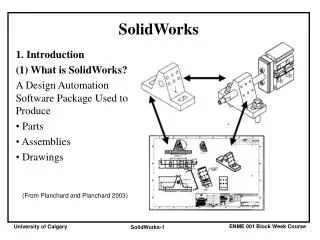
SolidWorks: Mirror, Revolve, and Circular Pattern. Introduction to Robotics. Let’s Review. At this point we have learned the following: Extrude Boss/Base Extruded Cut Adding Relations and Dimensions Linear Pattern, Shell, Offset Entities, and Fillets

SolidWorks: Mirror, Revolve, and Circular Pattern
E N D
Presentation Transcript
SolidWorks: Mirror, Revolve, and Circular Pattern Introduction to Robotics
Let’s Review At this point we have learned the following: • Extrude Boss/Base • Extruded Cut • Adding Relations and Dimensions • Linear Pattern, Shell, Offset Entities, and Fillets Our new goal is to learn how to apply the following features in the design of a simple gear • Mirror, Circular Pattern, and Revolve
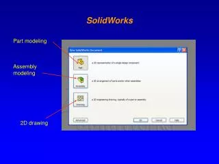
A simple 12 tooth gear Let’s Begin. Select NEW PART, then change the units to MILLIMETERS. Save the file as SIMPLE 12T Gear.
A simple 12 tooth gear Begin by selecting REVOLVE Boss/Base from the feature tool bar. Then select the FRONT PLANE.
A simple 12 tooth gear Begin by selecting the arrow next to LINE on the sketch tab of the tool bar. Choose CENTERLINE from the drop down menu. Draw a vertical centerline starting from the origin. End the line above the origin. The distance does not matter at this point.
A simple 12 tooth gear In property manager, make sure VERTICAL is shown in the relations box. Under OPTIONS check the box titled INFINITE LENGTH. Double check to make the parameters show 90 degrees. Then select the green check.
A simple 12 tooth gear Add a RECTANGLE using the sketch option of the same name from the tool bar to the RIGHT of the construction line. Select the MIDPOINT of the left side of the rectangle and add a COINCIDENT relation with the ORIGIN.
A simple 12 tooth gear Smart Dimension the bottom of the rectangle to 5.125 mm and the right side to 12.5 mm. You should now notice that the sketch is FULLY DEFINED. Then EXIT the SKETCH by clicking on the purple check/pencil in the top right corner.
A simple 12 tooth gear The revolve feature will then make MANY rectangles all around the centerline axis. This is very similar to extrude boss/base ( which we could have easily used) however there are instances where revolve many be more appropriate. Click the green check in property manager.
A simple 12 tooth gear Choose EXTRUDED BOSS/BASE from the features tab. Select the TOP surface of the gear them switch your ORIENTATION to NORMAL TO. Draw circle starting from the origin and dimension it to 6.4 mm. It will be fully defined at that point.
A simple 12 tooth gear Exit the sketch and change your view to ISOMETRIC. Enter 1.5 mm for the extrude distance above the surface of the gear. Then select the green check. Highlight the feature you just made. The select MIRROR from the toolbar.
A simple 12 tooth gear At first it wants to know along which PLANE you want to mirror around. To select this you need to expand the part features in the actual design area here. Select TOP PLANE.
A simple 12 tooth gear If you do it correctly, you will see the plane as well as the feature mirrored about this plane. Click the green check.
A simple 12 tooth gear Select the outside surface edge of your part and click SKETCH from the toolbar.
A simple 12 tooth gear Switch your view to NORMAL TO . Draw a CONSTRUCTION LINE from the origin to above the part. In property manager, make sure you choose INFINITE length. Add a COINCIDENT relation with the construction line and the origin then click the green check. ZOOM in to the top part near the construction line and choose arrow next to the ARC from the sketch toolbar. Choose 3 point arc from the menu.
A simple 12 tooth gear 2nd point 3rd point 1st point To make the 3 point arc you must click in 3 places. The first is on the top edge of our part to the left of the construction line. The second point is above your part and the 3rd is considered the midpoint of your arc. The click the green check in property manager.
A simple 12 tooth gear On the sketch toolbar choose MIRROR ENTITIES. For entities choose by clicking on your arc. For the section on MIRROR ABOUT click on the construction line. This will create an identical arc on the opposite side of the construction line.
A simple 12 tooth gear You should now see those items in property manager. Click the green check. You should see the following below.
A simple 12 tooth gear Click the 3 point arc from the sketch tool bar. The first point is left bottom point of the first arc. The second point is the right bottom point on the mirrored arc. The third point is a position for the midpoint. Click on the centerline as shown. Click the green check. 3rd point 2nd point 1st point
A simple 12 tooth gear Click the LINE tool on the sketch tool bar. Connect the top 2 points of the arcs together. Click on the top 2 points of each arc using the CTRL key and add a HORIZONTAL relation. Smart dimension the top horizontal line to 0.800 mm and the left arc with a radius of 3.60 mm.
A simple 12 tooth gear Dimension the top point of the left arc 8.60 mm with the origin. Smart dimension the bottom points of each arc to 1.70 mm.
A simple 12 tooth gear Click on the outside circumference of the main gear then using the CTRL button click on the lower 3 point arc. Choose CORADIAL to add this relation. Select the green check. You should now see the sketch is fully defined.
A simple 12 tooth gear Click on the Sketch you just made then chose EXTRUDED Boss/Base from the Feature toolbar. From property manager click the button under DIRECTION. This will reverse the direction of the extrude. From the direction menu choose Up to surface. For the surface, click on the opposite face of the gear. See next slide for visual. You may need to switch to ISOMETRIC.
A simple 12 tooth gear Click the green check to complete the extrude.
A simple 12 tooth gear Click on the feature you just finished then click on the arrow next to linear pattern. Choose CIRCULAR PATTERN from the drop down menu. In property manager, the first parameter is around which point the pattern should move about. Click on the central axis of your part. Check the box EQUAL SPACIN. Enter 12 for the # of instances. 360 degrees should be set if not already as shown.
A simple 12 tooth gear Click the green check.
A simple 12 tooth gear You have just finished making a 12 tooth gear. Finish this assignment by making a SolidWorks drawing. Turn this drawing in for grading.