CONVENTIONAL SHAFT SINKING B MANUAL MEANS
380 likes | 959 Vues
CONVENTIONAL SHAFT SINKING B MANUAL MEANS. SUBMITTED BY: Md fahad ahmad. CONVENTIONAL SHAFT SINKING BY MANUAL MEANS.

CONVENTIONAL SHAFT SINKING B MANUAL MEANS
E N D
Presentation Transcript
CONVENTIONAL SHAFT SINKING B MANUAL MEANS SUBMITTED BY: Mdfahadahmad
CONVENTIONAL SHAFT SINKING BY MANUAL MEANS • Conventional or ordinary shaft sinking methods are used when the shaft is to pass through strong, relatively dry rock, when the water in the face can be easily handled by sinking bucket or pumps and the shaft walls stand well with or without temporary supports • The conventional shaft sinking operations include the following three different types of work: • The main work of drilling-blasting loading the muck, supporting the sides and shaft equipping. • Subsidiary work including hoisting, pumping, ventilation and lighting. • Services such as power supply, water supply, transport, stores, repairs, housing etc.
Contd. • The main work at no.1 particularly the loading of muck can either be done manually or by mechanical methods. • Manual method of shaft sinking give very low progress (of the order of a foot per day) and can only be adopted for shallow and small diameter shafts. • For sinking a shaft of 5.5m finished diameter and 150m depth through normal coal measure strata the different operations involved and arrangements needed are described below:
PREPARATORY WORK: • The chosen shaft site to be connected by all weather Road and a network of roads to be constructed within the site for efficient transport. • Adequate power supply and water supply to be made available. • Surface general plan to be prepared showing both permanent and temporary service and residential structures (temporary structures must be so located as not to interface with permanent structures to be built later) roads, dump yard etc. • Fixing the centre of shaft and its axes, bench mark etc. With the help of permanent survey point at locations where these are /the area not disturbed. Contour plan of /at 1m internal for 250-500m from the shaft. • The site wherever needed is leveled and temporary structures on surface are erected.
SINKING EQUIPMENTS: The major items of plant include the following: • HEADGEAR: With pulleys for winding rope, suspended platform, pumps, power and lighting cables. Lever operated folding "v" doors built into the structure with chute at 15 to 20 ft. above ground level for facilitating the muck disposal. • Electric winding engine and mobile crane-1 no. each • Non-spinning type winding ropes with suspension gear consisting of clivy hook, lifting cone, detaching hook, capel and rider. Ropes for suspending platforms and other items. • Bucket or Hoppits of 0.75m3 to 1.0m3
Contd. • Fabricated platforms: (a)Working platform with opening for the shaft mouth. The opening is provided with doors.(b)Suspended platform: with openings for the buckets to pass is kept suspended in the shaft with non-spinning ropes 25 to 30 ft. above the shaft bottom. This provides safety to workmen in the shaft and stage for lining. Its suspension ropes also act as guides for the bucket. • Compressor for providing 25cu.m.per.min. Air at 14 kg/per sq.cm. Pressure for drills and face pump. • Compressed air drills- 8 nos. and pneumatic picks- 6 nos. • Compressed air face pumps- 4 nos. • Electric pumps for stage pumping.
Contd. • High water gauge (300mm) electric fan which can supply 8,000 cfm.air which is equivalent to 4m3/s. • Concrete mixer- 1 no. and shuttering segments for shaft lining • Ventilation tubes- 450mm in diameter. • 150mm pipes for compressed air, 100mm pipes for dewatering, and 150mm pipes for concrete transport in the shaft. Flexible ventilation duct reinforced flexible pipes for concrete placing, rubber hoses for drill machines. • Trolleys/dump truck for muck disposal on surface. Explosive and store van. • Cables for power supply, lighting and shot firing. Hanging light clusters. Transformers, switch gears etc.
Contd. • Signaling arrangements. • Slow speed winches for suspending platform and cables in the shaft. • The main items of consumable stores include the drill rods, explosives, cement and steel for reinforcement.
Direct Personnel: Face supervisors and workmen for face and surface are listed below:- • Managerial and other personnel needed for administration, office work, stores, medical and security etc. have not been shown here.
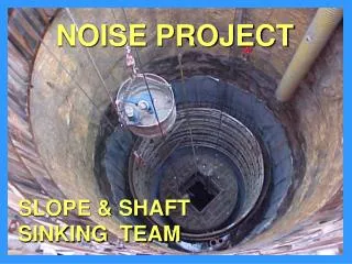
Sinking up to rock and construction of shaft collar • The perimeter of the area to excavated (finished diameter plus collar thickness) is pegged out. • Loose soil is dug directly, harder ground is broken with pneumatic picks and light explosives are used in still harder formations. Muck is loaded manually in buckets and hoisted up with crane. Sides are supported temporarily as excavations proceeds. • Shaft collar is built from strong bed-rock with reinforced cement concrete. The crane can be used up to 30 m depth. • Installation of winder, head frame, folding door at shaft top, winches for platform etc. and other plants on surface and suspended platform etc. in the shaft is completed at this stage for subsequent sinking operations. Arrangements are shown in fig.1 and fig.2.
Sinking through Lower Strata: The cycle of operations consists following phrases: 1. Drilling at face. 2. Blasting and defuming. 3. Loading the muck out and disposal at surface. 4. Erection of shaft lining. 1. Drilling: Holes forming a cone or pyramid cut are drilled in concentric rings with pneumatic drills. The number of rings is 4 to 7 depending on the shaft diameter. A pattern is shown in fig.3 to provide an excavated shaft diameter of 6.6 m and a pull of about 1.2 m. The hole density is 2 holes per m2 of shaft face. 2. Blasting and Defuming: For blasting purposes either gelignite or permitted explosives are used depending upon whether strata passed through are non-glassy or glassy in nature. Millisecond detonators are used for firing the successive rings of holes from the centre of the shaft to its periphery.
Explosive consumption is 1 kg per m3 with gelignite and 1.6 kg per m3 explosives. Consumption of detonator is 1 no per m3 of rock blasted .Some time is allowed for clearing of the smoke from inside the shaft before sinking operations are resumed. 3. Loading of muck: Blasted muck is filled into the buckets at the shaft bottom by hand-shoveling. On surface, the bucket discharges the muck over the”V” door chute to be loaded into trolleys or dumper for disposal at the dump-yard.
4. Erection of shaft lining: • Monolithic concrete lining is inserted after every fourth blast i.e. once 4.8 m progress has been made. On the base prepared at the shaft bottom ring of shuttering consisting .75 m high segments is erected, leveled and centered. • Concrete, which is transported down the shaft in steel pipes, is poured behind the shuttering with the help of flexible pipe from the suspended platform. Further rings are added to complete casting of the 4.8m length of lining. • The shaft side, before inserting the concreting lining if need be is supported with steel rings with lagging planks packed at the back. These are removed gradually when permanent lining is built.
Subsidiary works in the shaft:- • Pumping: - small quantity of water is bailed out in the bucket. For large quantities a combination of compressed air face pump and electric stage pump is used. • Ventilation: - High water gauge (300mm) fan is installed on surface, which supplied 8000 efm. Air through steel ducts to the face. Flexible duct is used at the end of steel duct which can be raised up at the time of blasting. • Lighting: - Cluster of bulbs is connected at the end of cable suspended from the cable drum on the surface and hung over the shaft bottom to provide flood light at the face. Fixed lights are also provided at other strategic places in the shaft. • A separate shot firing cable is hung in the shaft well clear of lighting and power cable. • The pipes of drainage, ventilation compressed air and concrete are securely supported on the bun tons fixed in the shaft side at regular intervals or with rag-bolts grouted in the shaft wall. Extension of these service lines is done from time to time as the sinking of shaft proceeds.
Cycle time for 1.2m pull • Drilling of holes (about 60) charging, blasting and defuming 8 hours • Loading out muck and miscellaneous activities 48 hours 56 hours • Time for total progress of 4.8 m 224 hours • Inserting the lining including erection of shuttering centering etc. 16 hours 240 hours • Number of cycles in 25 working days = (25*24)/240 = 2.5 cycles • Progress in 2.5 cycles= 2.5*4.8=12.0 m • Average monthly progress would be about 75% of 12.0 m = 9.0 m
DEEPENING OF EXISTING SHAFT A regular coal winding shaft 6.0 m in diameter has to be deepened to touch the bottom seam 100 m below without affecting normal winding operations. Describe a suitable method. • Major equipment: 1. Electric winding engines 2 2. Hoisting sheaves 2 3. Sinking buckets 3 4. Single tub cage 1 5. Tubs 6. Jack hammer 6 7. Pneumatic picks 4 8. Pneumatic face pumps 2 9. Electric pump 10. Platform with folding doors for shaft top 11. Shuttering for concreting 12. Pipes, cables, ropes etc
Deepening operations • Small shaft “A” is sunk near the coal winding pit on the side, away from main haulage level. Head room is made for installation of winding sheaves of the hoist “E”. The depth should be enough to reach beyond the sump of old shaft, cross the safety rock plug “p” and allow sufficient head room for the installation of the sheaves of second hoist is driven. • Level road way “L” to the position os shaft deepening. The place is widened and heightened for installation of winding engine “H” its sheaves and other equipment.Additional hoists are installed for carrying the suspended sinking equipment. • The shaft centre is marked accurately by correlation through the shaft “A”. The perimeter to be excavated is marked on the rock surface. • After deepening the shaft to some depths the platform with folding doors is installed at its mouth. • Sinking proceeds in the normal manner. The rock from sinking buckets is dumped into mine tubs and hauled up through shaft A. The debris can be packed into underground galleries or hoisted to surface through the main winding shaft for disposal. • On completion of sinking plug P is removed in sections.
2 holes/m2 of shaft, explosive-Ajax G. 1.6 kg/cu. m. Rock 1 kg/m3 for Celignite. • Detonator: 1 detonator /m3 rock • Holes in usual ring pattern: milli second delay detonators to be used . • Firing could be in series or parallel .Parallel firings has given very good results .On wooden pegs two bare wires are installed at the shaft bottom to form the bus bars. All detonators are connected to these two bus bars in parallel. The bus bars are connected by blasting cable to the suspended blasting cum lighting cable .This cable is energized from mains on surface at 440 volts through an apparatus allowing the current to flow for 4 m.s. only .
CALCULATIOS: (25*24)/50=12 Progress in 12 cycles-12*3=36m Average monthly progress would be about 75% of the above 36*0.75=27m