Establish Cost/Schedule Performance Impacts
Establish Cost/Schedule Performance Impacts. Evaluate Risk Handling Options. Program Requirements. Assess Risks. Establish Cost Schedule/ Perf Impacts. Manage Risks. Evaluate Subcontractor Risks. Estimate Effect On Cost. Identify Key Ground Rules. Establish Management

Establish Cost/Schedule Performance Impacts
E N D
Presentation Transcript
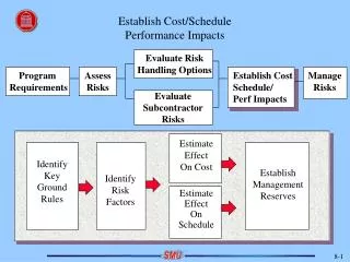
Establish Cost/SchedulePerformance Impacts Evaluate Risk Handling Options Program Requirements Assess Risks Establish Cost Schedule/ Perf Impacts Manage Risks Evaluate Subcontractor Risks Estimate Effect On Cost Identify Key Ground Rules Establish Management Reserves Identify Risk Factors Estimate Effect On Schedule
Changing Acquisition Environment • Aeronautics Systems Center has implemented a new proposal evaluation process. • What’s In - New low cost criteria termed “Most Probable Life Cycle Cost.” • What’s Out - Credibility of “single point estimate” in contractor bid.
Who Is “Low Cost” In the Example Below? ASC Assessment of Most Probable Cost (i.e., 50%) ASC Assessment of 90% Cost Confidence Contractor Bid Contractor A 8M* 10M 12M 15M 14M* 15M 20M 18M 16M* Contractor B Contractor C
What is Most Probable Cost Based On? Answer - The 90% cumulative probability span time in the government’s Most Probable Schedule. How does the government prepare a “Most Probable Schedule”? They perform a risk assessment of our proposal and map the risk into our proposed schedule.
What Are The Impacts Of the New ASC Source Selection Process? 1. Schedules will need to be prepared early in the proposal development cycle. 2. Risk should be identified and mapped to the proposed schedule. 3. A Most Probable Schedule should be developed and “pushed” to the left to help squeeze out cost.
OUTLINE What is a Scheduled Risk? What is the purpose of Assessing Schedule Risk? How can an assessment of Schedule Risk be Performed? Examples of Schedule Risk Assessments(SRA) How can we use SRA during: Pre-Proposal Discussions Proposal Development Contract Implementation What are the tools with which to perform SRA?
What is a Schedule Risk? Definition The likelihood of a schedule delay and the magnitude of the delay. Note: Schedule risk can be characterized as high, medium, or low depending on the level of disruption to the program schedule.
Purpose of Assessing Schedule Risk • Verify that schedule risk drivers have been accounted for (i.e., concurrency of design/test/production, interrelations between tasks and teams, requirements stability, etc.). • Provide basis to evaluate worth of schedule risk abatement options.
Common Schedule Risk Factors • Concurrency (Design/Test/Production) • Interrelations (between IPD Team/Functions) • Funding (Timely Turn-On) • Requirements Availability • Requirements Stability • Degree of state-of-the-art • Commonality with previous systems • Number/historical performance of subcontractors • Lead times (materials, etc.) • Amount and complexity of software required • Number and complexity of engineering drawings • Testing requirements (Timely Development) • Tests (number of hours\ required or number of successful flights) • Amount of new materials being used • Facilities Availability • Manpower Availability • Equipment Availability • Producibility Improvements • Urgency/priority of the program • Contractual incentives for meeting program schedule
Schedule Risk Assessment Methods 1. Experience Based Reviews - Recollection of lessons learned from similar work. 2. Technical Content Assessment - Analysis of empirical data on specific tasks. 3. System Level Modeling/Simulation - Computer-based representation of schedule.
Technical Content Assessment Example 1 What is the expected schedule duration for a 500 hour durability life test on an avionic subsystem given that a large number of spare subsystems are available? 500 hr 8 hr/day = 62.5 days ? ?
Technical Content AssessmentExample 1 (Cont.) Analysis of data on a similar avionic subsystem test shows that when: Mean time between maintenance action is 3.5 hr Mean time to remove and restore is 19 hr, and Test facility availability is 80% Schedule Duration is 502 days!! What if the number of spares is limited?
Technical Content Assessment Example 2 Simulation Flow Start Running this simulation flow repeatedly and plotting the results in a histogram format is a Monte Carlo simulation technique for estimating the calendar time and generating a final schedule estimate for conducting a durability test. Compute run time to failure Run Times Met 500 hour req’t? Y Stop N Compute remove repair and restore times Compute remove and restore times Spare available ? Y N Down times & # failures
Technical Content AssessmentExample 2 (Cont.) 120 100 80 60 40 20 Assumptions: 500 hour Dur. Test No Spares Limitation 3.5 hour MTBMA # of Occur- rences 0 376 399 421 444 466 489 512 534 557 580 602 648 Test Duration (Days)
Technical Content AssessmentExample 2 (Cont.) 800 750 700 650 600 550 500 450 400 90% Mean 10% Test Duration (Days) ($) 0 1 2 3 4 5 6 7 8 # Equivalent Ship Sets ($) (1000 Monte Carlo runs)
How to Leverage Applications of SRA Pre-ProposalDiscussions ProposalDevelopment ContractImplementation Experienced BasedReviews Technical ContentAssessment High RiskTasks High RiskTasks High RiskTasks As Required to Defuse Complex Issues As Required to Defuse Complex Issues System LevelModeling/Simulation Discretionof P.M.
Risk+ - Add-on tool for Microsoft Project @Risk – Add-on tool for Microsoft Excel
Types of Trade Studies • Controlled Convergence - Preliminary Method Used by Engineering. Quick Method to Compare “Primitive” Design Variables • Cost Effectiveness - Links Force Structure Implications to Top Level Requirements Analysis • Comprehensive - Considers all Applicable Decision Criteria
Time Frames For Trade Study Methods --Comprehensive-- ------Cost-Effectiveness------- -Controlled Convergence- Production & Deployment Pre Concept & Tech Dev A B C Concept & Technology Development System Development & Demonstration Operations & Support
Steps in Applying ControlledConvergence Method 1. Design Alternatives to Same Level of Detail 2. Choose Comparison Criteria 3. Choose a Baseline for Comparison Purposes 4. Compare the Alternatives to the Baseline 5. Sum Pluses and Minuses 6. Can New Alternative Be Created by Changing Negative(s) of a Strong Alternative? 7. Can Weak Alternative Be Eliminated? 8. Return to Step 4 or Document Findings and Proceed
Controlled Convergence Method For Preliminary Trade Studies Design Alternatives 1 2 3 4 5 Comparison (Baseline) Criteria (Design Primatives) Thrust/Weight (T/W) S – S – + Weight/Wing Ref. Area (W/S) S – – + + Coef. of Lift (C ) S – + – – L Cruise Performance (Specific fuel S S + S + consumption, range, speed) Observables (Shaping, materials, S S + S – propulsion, etc.) Payload Capacity S – + – S Agility (maneuverability & S + + – + controllability) ... TOTAL +'s 0 1 5 2 4 TOTAL S's 7 2 1 1 1 TOTAL –'s 0 4 1 4 2 + Significantly Better Legend S About the Same – Significantly Worse
Strengths and Weaknesses of Controlled Convergence Preliminary Trade Study Method • Difficult for Strong-Willed Person to Dominate Decision Making • Encourages Development of Additional Design Alternatives • Time to Converge Can Be Controlled Repeated Applications of This Method Will Result in “Fuzzy” Comparisons of Leading Alternatives
PLUS PLUS PLUS PLUS • Management • Tech Data • Initial • RDT&E • Operations & • Hardware • Publication Spares • Facility Support • Software • Contractor Service Construction (Includes • Nonrecurring "Start-up" • Support Equipment Post-Produc- • Allowance for Changes • Training Equipment tion Support) • Factory Training FLYAWAY COST • Disposal WEAPON SYSTEM COST PROCUREMENT COST PROGRAM ACQUISITION COST LIFE CYCLE COST Life Cycle Cost Composition BV41861
Cost Estimating Methods UsedDuring Acquisition Phases Pre Concept & Tech. Dev. Concept & Tech. Dev. Early in System Dev. & Demonstration Early in System Dev. & Demonstration P = Primary S = Secondary Prod. & Dep. Parametric Analogy Bottom- Up Eng. P S S N/A N/A S P S N/A N/A N/A S P P P
Relative Values of LCC Elements(based on 100 aircraft) Life Cycle Cost Operations & Support (46.1%) RTD&E (4.3%) Procurement (49.6%) 0.30 Demo/Validation 2.12 Air Vehicle 0.13 Engine 0.22 Offensive Avionics 0.70 Launcher 0.02 Training 0.06 Special Support Eqpt 0.47 Test & Evaluation 0.15 Project Management 0.13 Data 0.59 Tooling & Engineering 31.52 Airframe 8.83 Engine 2.31 Offensive Avionics 2.18 Launcher 0.17 Training 1.94 Special Support Eqpt 0.36 Test & Evaluation 0.07 Project Management 0.15 Data 1.52 Initial Spares 1.74 Replenish Sppt Eqpt 10.72 Fuel 0.92 Base Level Maint. 11.55 Depot Maint. 3.70 Updating/Mods 0.78 Replenish Spares 0.06 Vehicular Eqpt 12.61 Military Personnel 0.46 Civilian Personnel 1.29 Support Personnel 2.23 Pipeline Costs
Principal Steps in ComprehensiveTrade Study 1. Identify Decision Criteria within Broad Decision Categories 2. Quantify Decision Criteria for Each Configuration 3. Analyze Customer Preferences for Each Decision Criterion 4. Assign Weights to Decision Criteria 5. Score Each Configuration (Sum Weights x Preferences) 6. Perform Sensitivity Analysis on Weights If Configuration Scoring Is Close
Sample Configuration Decision Categories Air Vehicle Cost Risk Effectiveness Threat Acquisition Avoidance Hit Avoidable Given Acquisition Sortie Survival Given Hit Target Acquisition Target Kill Given Acquisition Kills per Sortie Targets Killed Over Time Flyaway Weapon System Procurement Program Acquisition Life Cycle Technical Cost Schedule Producibility Supportability Management
Utility Functions - Preference Indicators • Utility Functions Provide a Good Technique for Translating Diverse Criteria Into a Common Scale. (i.e., Range in NMi, MTBF in Hours, etc.) • Utility Scores Range From 0 to 1 With 0 Being Least Preferred and 1 Being Most Preferred. Examples Utility for Range Utility for MTBF 1 1 Threshold Objective Threshold Objective Range in MNi MTBF in hours
Hints for Determiningthe Shape of Utility Functions 1 After Establishing the Minimum Requirements and Goal, Draw Neutral Preference Position as Shown Neutral Preference 1 Critical, Risk Prone Non-Critical, Risk Average Req Decision Factor Goal 1 Divide Decision Factor into Quartiles and Assess 25%, 50%, and 75% Points Relative to Neutral Preference 2 Req Decision Factor Goal
Sensitivity Analysis ofConfiguration Preferences • Select Factor of Interest Such as Performance Range • Increase Weight for Factor of Interest Until the Preferred Alternative / Configuration Changes • Incrementally Lower the Weight for Factor of Interest Until the Preferred Alternative / Configuration Changes
Exercise Background: As system requirements are identified and flowed down form the SDR, design options for the Group A hardware must be identified and trade studies performed to determine the best design. Five design options have been developed for Group A and have been evaluated by the AFS design team. Documentation of this first pass design review by the team is presented below and must now be used to select the best design in support of entrance criteria for the program PDR. Exercise: In order to limit the scope of this Exercise, the design trade study will be restricted to the Aft Antenna and Radome assembly. Referring to the Introductory Briefing material presented on the four subsequent charts, the Statement of Customer Requirements Part 2, and the Aft Antenna/Radome Functional Requirements Baseline, evaluate the designs provided and perform a comprehensive trade study to select the best design.
AJS Statement of Customer Requirements Customer: Kurdish Fighter Program (Peace Whey) Operational Need: Fighter aircraft operating in a hostile environment require extensive electronic countermeasures (ECM) to defeat air-launched and ground-launched threats to the survivability of the aircraft. These ECM systems must be capable of generating and broadcasting radio frequency (RF) energy at sufficient power levels and in appropriate patterns to defeat any threat encountered by the aircraft.
AJS Statement of Customer Requirements(Cont.) • Description: The AJS shall be capable of installation on a lightweight, high-speed, multi-role fighter and shall be supportable in primitive forward operating bases. The system shall be capable of transmitting radio frequency signal in the microwave frequency range at sufficient power levels and in patterns capable of successfully jamming all identified threats at the required operational range. The AJS system shall consist of the following major components: • 1. Core Avionics: Shall consist of the jammer, the radar warning receiver, and the OFP software. Shall be capable of generating the required RF signal in the microwave band at required power levels and of detecting radar emissions from the threat set at the required ranges. • 2. RF Switch H/I/J Band: Shall control selection of broadcast frequency bands as required. • 3. Fire Control Radar Notch Filter: Shall prevent interference of the Fire Control Radar (FCR) by the AJS system. • 4. Forward Transmit Antenna • 5. Aft Transmit Antenna and Raydome • 6. WRD-650D24 Waveguide • 7. Coaxial Cable
AJS Statement of Customer Requirements(Cont.) • Schedule: • 1. Flight Test: The Safety of Flight(SOF) unit for flight test shall be available for installation 26 months after program go-ahead. • 2. First Production Delivery: The first production assembly shall be delivered 36 months after program go-ahead. • 3. Delivery Rate: Delivery of AJS units shall be at the rate of 2 units per month. • 4. Total Quantity: The total quantity of AJS units shall be 20. • Customer Priorities: • 1. Power Transmitted. • 2. Weight • 3. First production delivery. • 4. Cost not to exceed $125,000/unit (for 20 units).