Velocity Measurement
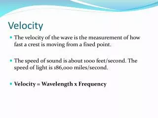
Velocity Measurement. Electromagnetic Linear-Velocity Transducer. An electromagnetic linear-velocity transducer is composed of a stationary coil with a permanent-magnet core moving within the coil. The core is attached to the object whose velocity is to be measured.

Velocity Measurement
E N D
Presentation Transcript
Velocity Measurement Electromagnetic Linear-Velocity Transducer An electromagnetic linear-velocity transducer is composed of a stationary coil with a permanent-magnet core moving within the coil. The core is attached to the object whose velocity is to be measured. When the core moves, magnetic lines of the field created by the core cross the turns. An electromotive force induced in the turns is proportional to the speed of the core
Linear Velocity • Moving a magnet through a coil of wire will induce a voltage in the coil according to Faraday's and Lenz' Laws. This voltage is proportional to the magnet's velocity and field strength. During operation in the working range of the transducer, both ends of the magnet are inside the coil. • With a single coil this would give zero output because the voltage generated by one pole of the magnet would cancel the voltage generated by the other pole.
Linear Velocity….. • To avoid this, the coil is divided into two sections, so the N (North) pole of the magnet will induce a voltage in one coil and the S (South) pole will induce a voltage in the other coil. These two coils are then connected in series-aiding, to obtain a DC voltage output proportional to the magnet's velocity.
Linear Velocity…..LVT in series For series operation, the blue and green leads are tied together and the output is taken from the black and red leads. With the coils wired in series, the output is summed, producing the maximum sensitivity. Besides a high sensitivity, the transducer exhibits excellent noise immunity, attributed to the coils being wound in series opposition. Noise generated on one coil will be equal in magnitude but opposite in polarity to the other coil.
Linear Velocity…..LVT in parallel Parallel operation is achieved by tying the black and blue leads together, and the green and red leads together. The two connections create the terminals for the output. This configuration cuts the sensitivity in half, and reduces the source impedance by a factor of 4. The benefits of this arrangement are: lower output, for use in high speed applications; lower output impedance, for compatibility with electronics with a low input impedance, and higher frequency response for a given load impedance
Velocity by Doppler effect The Doppler effect (or Doppler shift), named after Austrianphysicist Christian Doppler who proposed it in 1842, is the change in frequency of a wave for an observer moving relative to the source of the wave. It is commonly heard when a vehicle sounding a siren or horn approaches, passes, and recedes from an observer. The received frequency is higher (compared to the emitted frequency) during the approach, it is identical at the instant of passing by, and it is lower during the recession
Doppler Effect…Sirens • The siren on a passing emergency vehicle will start out higher than its stationary pitch, slide down as it passes, and continue lower than its stationary pitch as it recedes from the observer
Velocity by Doppler Effect • In classical physics (waves in a medium), the relationship between observed frequency f and emitted frequency f0 is given by: • where • is the velocity of waves in the medium • sis the velocity of the source relative to the medium • ris the velocity of the receiver relative to the medium Change in frequency Observed frequency