Introduction to MODFLOW
270 likes | 334 Vues
This article provides an introduction to MODFLOW, a groundwater flow model. It discusses the block-centered grid and the calculation of conductance using the harmonic mean. It also explains the default boundary conditions and the usage of vertical conductance terms. The article covers different types of layers and the input of grid spacing in MODFLOW. Additionally, it provides examples of solution techniques and explains the required input for the BAS package.

Introduction to MODFLOW
E N D
Presentation Transcript
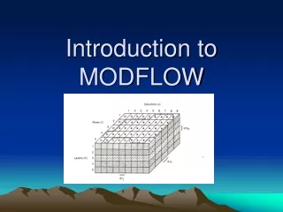
i-1 i i+1 xi-1/2 xi+1/2 General 3D equation used in MODFLOW Block centered grid xi
K values in the space between nodes is calculated using the harmonic mean
The default boundary condition is no flow. (active nodes)
No flow boundary Imaginary nodes K=0 (i+1) (i,j,k) K=0 K=0 = 0
Conductance Darcy’s law
In general, conductance = KA/L Also: leakance = Kv/thickness resistance = thickness/Kv (resistance is an analytic element term)
Vertical Conductance Terms MODFLOW uses special terms (VCONT) for vertical conductance, which is required in 3D problems. Modflow.exe requires the user to supply values for the VCONT arrays. GW Vistas computes the values in the VCONT arrays for you. VCONT = Kv/z = Conductance/(xy) = “leakance”
Vertical conductance is defined using leakance, or VCONT in MODFLOW language. We also have horizontal conductance along rows and along columns.
See MODFLOW manual (p. 2-19) or 2nd ed. of textbook by Domenico & Schwartz (Eqn. 7.15) for MODFLOW’s FD equation
Types of Layers (LAYCON array) Confined Unconfined Convertible (Useful to think in terms of a layer transmissivity.)
h layer 1 bot layer 2 datum Conductance Confined layer transmissivity = (KRi,j-1/2,k)(vk) Unconfined layer transmissivity = (KRi,j-1/2,k)(hi,j,k-BOTi,j,k)
TOP BOT Input of Grid Spacing • MODFLOW asks for values of horizontal grid spacing • (i.e., r and c) but not vertical grid spacing (v). • Vertical grid spacing (v) is calculated by MODFLOW • from user supplied values of the bottom (BOT) • of each layer. (GwVistas asks for both top and bottom of • each layer.)
Note that a top unconfined layer actually has no top. The head value in the top layer could potentially rise to infinity. Land surface elevation is not used in MODFLOW, except in the ET package.
Examples of solution techniques that combine matrix solution with iteration: IADI (see chapter 5 of W&A) SSOR* SIP* PCG2* *Used in MODFLOW
m+1 Note: m is time level and n is iteration level. t m m-1 Schematic of solution procedure
The 3D eqn. with an implicit approximation generates a coefficient matrix with 7 diagonals
Coefficient Matrix for a model with 2 rows, 3 columns, 2 layers. Matrix is sparse and symmetric.
SSOR The coefficient matrix has 5 diagonals Coefficient matrix is Symmetric and banded
MODFLOW88/96 Packages required required head dependent BCs 1 is required & PCG2
Input assembly for the BAS Package