Download

1 / 18
190 likes | 288 Vues
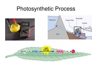
1. Photoacoustic Signals from Leaves As signature of photosynthetic processes Shmuel Malkin Biological Chemistry Department Weizmann Institute Rehovot 76100 Israel. General Introduction.

E N D
1. Photoacoustic Signals from Leaves As signature of photosynthetic processes Shmuel Malkin Biological Chemistry Department Weizmann Institute Rehovot 76100 Israel
General Introduction Photoacoustic (PA) signals - these are signals obtained from a microphone, or other pressure sensor, which is placed near an investigated object, irradiated by pulsed or periodically modulated light. For the case of periodically modulated light, which will be dealt here, the microphone signal is characterized by two parameters: its amplitude and phase-shift, relative to the amplitude and phase of the exciting light modulation, or equivalently its in-phase and quadrature amplitude components. These parameters (which will be explained later) are measured by a lock-in amplifier and recorded as a function of time. In this presentation and following ones I shall deal with objects that perform photosynthesis, or partial reactions of photosynthesis. The characteristics of PA signals obtained from such objects and the use of PA measurements to study photosynthesis will be described.
There are two main mechanisms, which produce PA signals from photosynthetic systems, which are usually superimposed. (1) Photothermal mechanism - The modulated (or pulsed) light results in modulated (or pulsed) heating of a light absorbing sample. The sample releases the heat into the air-phase around it. The air phase is heated during the light-on period and cools in the light-off period. Corresponding pressure changes occur, which are sensed by the microphone and converted into PA signals. (2) Photobaric mechanism - in plant photosynythesis oxygen is produced by light absorption and is ultimately released into the air phase, while carbon dioxide is taken up from the air and utilized to make organic compounds. The use of modulated (or pulsed) light results in corresponding pressure changes, which the microphone senses and produce PA signals. While O2 production responds quickly to changes in light intensity, CO2uptake lags considerably, due to the intervening “dark” reaction of photosynthesis. Thus, photobaric signals due to CO2 uptake are vanishingly small. Photobaric signals are normally assigned to oxygen evolution alone. Under very special conditions, however, which will be discussed later, other types of gas evolution/uptake occur, giving rise to special PA signals. The following cartoon illustrates these mechanisms:
Two effects: conversion of heat and matter fluxes to pressure Thermal Effect Baric Effect
There are two sorts of samples: “liquidic”(e.g. aquaeous suspension, water infiltrated leaf, algal thallus)and “spongy” (e.g. normal leaf, lichen) The photoacoustic effect from “liquidic” samples results from thephotothermaleffect alone. This is because the diffusion path of oxygen in the liquid phase is relatively long, which results in almost total damping in its modulated release. MIKE LIGHT HEAT “Liquidic” sample
The photoacoustic effect in a ”spongy” sample is a superposition of photo-thermal and photo-baric effects The photoacoustic photobaric signal component usually reflects photosynthetic oxygen evolution MIKE HEAT LIGHT O 2
To probe photosynthesis by modulated light, it is mostly preferable to use light, whose intensity is sufficiently low - in the light-limiting range of photosynthesis - (this is the light intensity range where the rate of photosynthesis is approximately proportional to the light intensity - cf. later). The photoacoustic signal is compared in two situations: (1) using light-limiting modulated light alone. (2) adding non-modulated (called background) light to the modulated light. Usually, the background light is sufficiently strong, in the saturation range of photosynthesis - (this is the light intensity range where the rate of photosynthesis is maximum and is light intensity independent). In the 1st case, the photoacoustic signal reflects light-limiting state. In the 2nd case it reflectsphotosynthetic saturation. Notice, That The Saturating Background Light, Being Non-modulated, Does Not Give Rise To Any Photoacoustic Signal By Itself.
The Characteristics of the Rate of Photosynthesis vs. the Light Intensity (which are reflected in the PA signal behaviour) Rate Saturation range In this range the rate is constant. O2 evolution quantum-yield and Energy-Storage* tend to zero Light Intensity Light-limiting range In this range the rate is proportional to the light intensity. O2 evolution quantum- yield and Energy- Storage* are maximal *For the definition of Energy-Storage - see later
Lamp Lens Chopper Filter Lock-in Amplfier THE EXPERIMENTAL SYSTEM Background Light Source Modulated light Source Bifurcated light-guide Air Volume / Sample Window Clamping Screw O-ring Microphone PA Cell Body
PA signal Time The two components of the PA signal have different behaviours towards the addition of saturating background light: * The photothermal component usuallyincreases. * The oxygen evolution component is eliminated. Photothermal signal component Oxygen-evolution signal component Base-line Modulated light on Saturating background light on and off Notice, that inactive or inert (non photosynthetic) samples, are not usually influenced by background light
PA signal (Reminder from Previous slide) D S Modulated light on S Saturating background light on and off Time The behavior of the PA photothermal signal - Explanation Under light limiting conditions a significant amount of the light energy is stored in the chemical products of the photosynthetic process. Therefore, only part of the light energy is converted to heat. Under light saturation essentially all the light energy is converted to heat.* *A more refined analysis should bring fluorescence into account. The photothermal signal, being proportional to the rate of heat release, becomes therefore maximum upon the addition of saturating background light. The maximum value (S) is directly related to the total light energy. The difference between this value and the signal under light limiting conditions (D S) is related to the energy stored in photosynthesis. The ratio D S/S is the maximum “energy storage fraction” or simply “energy strorage” (ES). Since S is proportional to the photon energy (= h n = h c / l), the energy that each photon deposits, on the average, in the photosynthetic process is: E = (ES) x h n =(ES ) x h c / l h - Planck constant, n - light electromagnetic frequency, c - light velocity, l - light wavelength
PA signal (Reminder from a previous slide) Time The behavior of the PA photobaric signal (normally due to oxygen evolution) - Explanation Under light limiting conditions the rate of oxygen evolution is approximately proportional to the light intensity. Hence the rate of oxygen release is modulated maximally, following direcly the changes in the light intensity. Correspondingly, the PA photobaric signal amplitude is maximum. Under light saturating conditions, changes in the light intensity do not lead to changes in the rate of oxygen evolution. In consequence oxygen evolution is not modulated at all and the photobaric signal amplitude tends to zero.
How the PA signal is measured by the Lock-in amplifier Light Excitation time profile Light intensity Square - form modulated light Fundamental Fourier component A OR Time Electronic modulation B Time Microphone Response (Fundamental Fourier Component) Microphone signal C Time Time-lag Amplitude Excitation - may be modulated by a chopper, yielding a square wave pattern (trace A - in red). This has a Fourier fundamental component (trace A - in pink). Excitation may be also modulated electronically, yielding a sinusoidal pattern (trace B - in red). Although the ultimate microphone signal may be complex, the lock-in-amplifier essentially analyzes its fundamental Fourier component (trace C), and compares it to the fundamental Fourier component of the excitation profile (trace A - in pink or traceB). The measured parameters are the amplitude and the phase (proportional to the time-lag (see next slide). These two parameters depend on the modulation frequency, because of the time lag, which occurs between excitation and response, caused by intervening processes (photosynthetic dark reactions, diffusion of heat and oxygen, etc.). In general, the photothermal and photobaric signals have different phases and amplitudes. The combined signal cannot be calculated by adding the amplitudes. It is actually a vector sum of the individual components, as will be explained later.
How the PA signal is measured by the Lock-in amplifier (contd.) The fundamental Fourier component of the excitation, as shown in the previous slide can be expressed mathematically: E =Eosin (2pft),where E is the excitation intensity, Eo its amplitude, f is the frequencyand t the time. The resulting fundamental Fourier component of the response (microphone signal) is expressed as S =R sin (2pft + f). In this expression there is a specific time dependent part, with two relatively constant (or slowly changing) parameters: Amplitude, R, and Phase, f. Since the response lags after the excitation, f is negative. The lag time is equal to - (f / 2pf). R and f are simultaneously recorded by the lock-in amplifier. They might change slowly (relative to 1/f), following temporal changes in the energy storage and oxygen evolution. Obviously they depend on the condition of the sample. There is an alternative mathematical way to write the response signal: From basic trigonometry it follows that the expression S=R sin (2pft + f)can be combined from sinusoidal and cosinusoidalcomponents: S =R cos fsin (2p f t) + R sin fcos(2p f t) The values (R cos f)and R sin f), resp.are called respectively in-phase and quadrature. Their absolute value represent the amplitudes of each component. The lock-in amplifier can be set either to a measuremental mode where it records the total amplitude and phase or to a measuremental mode where it records the in-phase and quadrature, which is more suitable for PA measurements.
How the PA signal is measured by the Lock-in amplifier (contd.) In summary the PA signal can be represented by two parameters: These could be either its amplitude (R) and phase (f) or the in-phase (I) and quadrature (Q) values. The relations between the two are: I = R cos f; Q = R sin f The inverse relations are obviously: R = [(I)2 + (Q) 2] 1/2 ;f = arc tg I/Q The advantage of using the signal components I and Q is their additivity, when the total signal is a composition from different sources (e.g. photothermal and photobaric). I (total signal) = I (photothermal) + I (photobaric) Q (total signal) = Q (photothermal) + Q (photobaric)
PA signal measurement by the Lock-in amplifier (advanced) Mathematically, the two parameters of the signal in either mode can be viewed as representations of a two dimensional vector, whose x and y components are I and Q, its length is the amplitude R, and f is the angle that it makes with the x axis. y Q R f A B I x To complete the visualization of the signal, imagine that the signal vector (together with the coordinate system x,y), rotates counterclockwise around the origin, with an angular velocity 2p f (radians/sec), while the line AB remains stationary. If at time zero the x axis and the line AB coincide, the projection of the signal vector on the line AB is R sin (2p ft - f) i.e. the projection represents the complete signal with its time dependence.
PA signal parameters and manipulation (contd.) The same signal-vector can be placed in a different coordinate system x’,y’, which are rotated in a certain angle a relative to the original coordinate system. This is equivalent (according to the definitions of the previous slide) to time transformation, such that time zero is shifted. Evidently this transformation does not affect the amplitude. The transformed phase is the original phase plus a. The in-phase and quadrature components will be transformed accordingly. In practice this transformation is affected by the lock-in amplifier, which gives the possibility (by rotating a suitable knob) to add any angle a to the original phase. What is this good for? This may be practiced when the signal is a combination of photothermal and photobaric contributions. If we are interested in the photobaric contribution, we may adjust a, such that one of the signal components (e.g. the quadrature) does not have any photothermal contribution. This component is purely photobaric and can be used to study the properties of the photobaric signal alone. y In this figure, the vector signal is in black, its photothermal contribution is in pink and its photobaric contribution is in blue. By rotating the coordinate system such that the direction of the x’ axis is parallel to the photothermal contribution, no photothermal component exists in the y’ axis. The new quadrature (signal component in the y’ axis) has only photobaric contribution (blue). y' x x'
PA signal parameters and manipulation (contd.) This is how the PA signal is manipulated in the lab practice, in the case of a leaf measurement: 1. The in-phase and quadrature components of the signal are measured with an arbitrary setting of the lock-in amplifier*. 2. Saturating background light is applied (this nullifies the oxygen evolution component). 3. While saturating light is on, a phase adjustment is made continuously on the lock-in amplifier (which changes the values of the in-phase and quadrature components), in order to reach a situation where the quadrature signal is nullified. 4. The background light is turned off. The quadrature signal achieves a non-zero value, which is proportional to the rate of oxygen evolution. 5. Background light may be turned on and off several times to ensure the stability of phase and signal amplitudes. *Because the setting of the lock-in amplifier is arbitrary, there is already a “built-in” arbitrary addition to the phase-shift and the measured phase angle loses any relation to the time scale of the exciting light. For specific examples of real PA measurements see the next presentation: “PA measurements of leaves: I. Basic measurements”