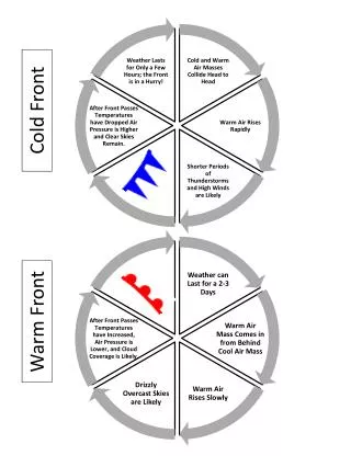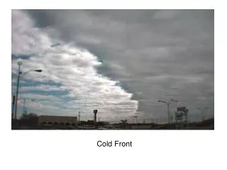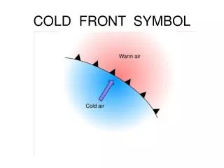
COLD FRONT END STATUS
COLD FRONT END STATUS. OUTLINE. RF Cryo System Mounting Apparatus 27-m cryo upgrades. Noise temps of < 50K from 1-18GHz 1% Amp Stability, 1 degree phase stability Polar accuracy: 15 dB isolation. RF System.

COLD FRONT END STATUS
E N D
Presentation Transcript
OUTLINE RF Cryo System Mounting Apparatus 27-m cryo upgrades
Noise temps of < 50K from 1-18GHz • 1% Amp Stability, 1 degree phase stability • Polar accuracy: 15 dB isolation RF System Need as much amplification as needed to satisfy power requirements of RF-fiber converter (which is 7dBm, requiring about 86dB of gain). Most likely 2 amps in addition to the LNAs.
Horns Single horn not available for cover full band. Dual-Pol horns with low spillover available from Sandy Weinreb’s lab that operate over factors of 6 in frequency. RF System
Horns Split into 1-6GHz and 3-18GHz. Physical size of 1-6GHz horn, means we can only easily cool the higher-frequency horn. RF System
Horns • Cost of tools for machining < $1K. • Cost for metal is < few $K (getting estimate) • Can make one large horn in 2 weeks. Ahmed Agkiray currently refining design (best design so far has aperture efficiencies of ~50% at highest frequency. Once design is complete, they will be machined at OVRO by TomiHovatta/Stan Hudson. RF System
Couplers Since there are before the LNAs, must have lowest insertion loss possible. They must also work at cryo temps. Available vendors are Krytar and Atlantec Cryo testing last week showed both perform at cryo temperatures, and IL reduces by 0.1dB at low frequencies and up to 0.4dB at higher frequencies. RF System
Couplers for 1-6GHz system The large size of Krytar 158020 requires a cable with right-angle connectors which increases the IL by 0.1dB. Resulting change in receiver temperature is 0.6-0.8K. Using Atlantec 1-4GHz gives rx temps 3K lower, but sacrifices 4-6GHz. RF System
Couplers for 3-18GHz system In this case, Krytar seems like the better option. NOTE: ATLANTEC components are manufactured in the UK. RF System
Low-noise Amplifiers Components with longest lead-time. These have already been ordered (~4K each) CIT1-12GHz amps have typical gain of 32dB and noise below 5K. Measurements from first 3-18GHz amps already built show a gain of ~35dB and noise below 10K across whole band. Should be delivered in December. RF System
Isolators Isolators are analogous to RF diodes: they let power go through over a given band but reject most of what comes back. These are necessary if the interaction of amps with subsequent components have poor matches leads to high reflection. This can cause standing waves which can induce oscillations. There are NO isolators available which work over the frequency we need, so one way to deal with reflections is by using attenuators. Depending on how much attenuation we need to use, this might require additional amplification to get to desired power levels. RF System
Secondary Amps We will need at least one stage of secondary amplification (and most likely two) Placing the secondary amp on the 77K radiation shield could lower the receiver temperature of the warm system by up to 5K**, so we would ideally want an amplifier that can be cooled to cryogenic temperatures. To save cost (buy in bulk), these should operate over full band. RF System
Filters (notch) Due to Sprint signal, we need a notch filter for 1.93-1.98 GHz. Rejection needed is >40dB (so it can go after 2nd stage amp) Only 3 vendors said they could make a notch filter that would still preserve the 1-6GHz passband. RF System
Filters (bandpass) The main advantage to having a bandpass filter is to reject RFI outside our band, which can be pretty severe. 4 vendors quoted us on bandpass filters. Info for low-frequency bandpass (1-6GHz) RF System
Filters (bandpass) The main advantage to having a bandpass filter is to reject RFI outside our band, which can be pretty severe. 4 vendors quoted us on bandpass filters. Info for HIGH-frequency bandpass (3-18GHz) RF System
RF Switch Over our wide bandwidth, we need a mechanical switch to change between the output between the two systems. James Lamb has tested many different companies and says many are unreliable. He suggests we use Dow-Key. Quote has been requested. Will need one for each polarization. RF System
Cryostat Design Cryostat must be able to house the full 3-18GHz system, and the components for the 1-6GHz system. Will use a CTI 350 Fridge-head for cooling Must allow for range of horn sizes. Should be as compact as possible 3-18GHz horn + fridge-head are main elements in determining its size. RF System
Cryostat – Physical Dimensions Pretty big, but not unwieldy (QUIET cryostat weighed 800 pounds and was a cylinder of diameter ~4 feet)!!! Ours is an L-shape rectangular box. 24”x18” with a 15”x7” rectangle chopped out of it. 9” total thickness. ~15” translation between horns, 1” focus diff. RF System
Cryostat – Walk Through RF System
Cryostat – Walk Through RF System
Cryostat – Walk Through RF System
Cryostat – Walk Through RF System
Cryostat – Status • Quote for cryo case was sent out last week -- should be in later this week. • Cryostat currently under review by James Lamb and Sandy Weinreb. All pieces insides the cryostat (cold plate, radiation shield, filter bank, G-10 supports, bracketry for components, thermal connectors) will be machined at OVRO. Cryo case too big for our machine shop. RF System
Still to finalize Whether location of horns is ok (from Sandy) Horn design Cost of machining. Components to use. Full Cost (including connectors and coax). • I plan on making the cables myself. (BeCu vs. SS). • Feed-throughs/connectors should be less than $1K. • Should have a lot more info next week. RF System
Prime Focus Apparatus Install a new self-contained system that bolts onto the ring platform. Uses tracks for linear (and vertical -- focus) translations with actuators in z, gears otherwise. Uses a gear motor for rotation. Adjust y once on installation. Mounting Apparatus
Apparatus Walk-through Mounting Apparatus
Apparatus Walk-through Mounting Apparatus
Apparatus Walk-through Mounting Apparatus
Apparatus Walk-through Mounting Apparatus
Apparatus Details Minimal info on dish distortion/focus change – makes it hard to define translation/rotation tolerances. So… Translation in x-axis: +-7” Translation in y: +-3” (fix) Translation in z: -4”->+7” Hard stops in x, z-range limited by actuators (up to 3000 pounds). Total weight (including screws) = 350lbs + receiver. Cost: ~$35K total (Tomi’s document) Still need Final PDR Getting quotes on parts we can’t machine at OVRO Mounting Apparatus
27-m Cryo Upgrades • Russ finishing up design of how to get cryo lines up to prime focus. • Compressor in pedestal. • He lines in the equatorial mount need a 4-port rotary union ($~5K) • 2-port rotary union at exit • Most straightforward part of whole upgrade! Cryo Upgrade
Cryo Upgrade Inventory Receiver Focus apparatus Compressor/Cryo lines Temp Controlled (TECA) box with: Bias for amps Temp Stable noise diode source Temp monitoring RF switch Pre-amp module RF-optical converter Ethernet Switch Ethernet controllable power supply Small computer to control Noise Diode, Bias, and Alignment jig (rotation, x, and z) Programming said computer/interface with CS.
September/October: Finalize Cryo design. Select (and order) RF components. Select rest of hardware insideTECA box. Purchase hardware needed for cryo upgrade. Start machining apparatus and cryostat. • November: Control subsystem development, testing of individual RF components (as they arrive), machining of rest of apparatus and cryostat. Begin machining horns. • December: Cryostat machining complete. Begin cryo testing in lab. • January: Apparatus machining complete. Begin testing of apparatus with control system. He line installation complete. • February/March: Extensive testing of Cryostat/Apparatus • April: Installation? Could be done earlier depending on results from Feb/March. • May: Science! ;-) Timeline