Download
1 / 79
1.5k likes | 2.26k Vues
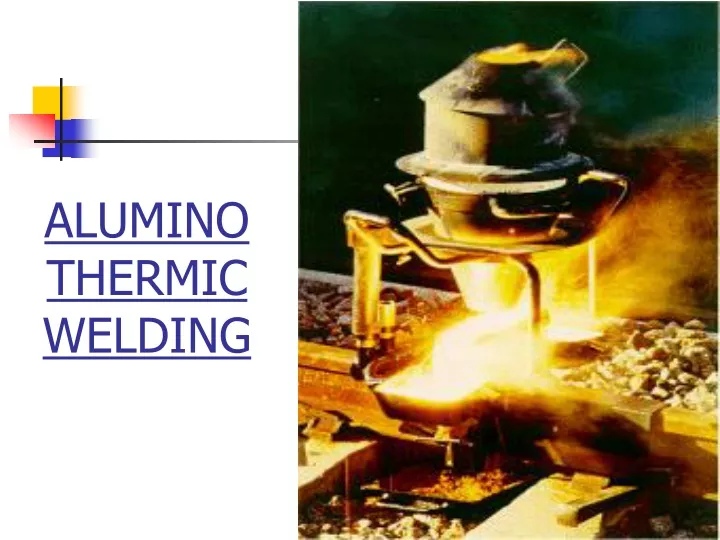
ALUMINO THERMIC WELDING. CODES & MANUALS. Manual For Fusion Welding Of Rails By Alumino Thermic Process Revised (2012) up to CS 1 Indian Railway Standard Specification For Fusion Welding Of Rails By Alumino Thermic Process Revised (IRS-T-19-2012 up to CS 2 ).

E N D
CODES & MANUALS • Manual For Fusion Welding Of Rails By Alumino Thermic Process Revised (2012) up to CS 1 • Indian Railway Standard Specification For Fusion Welding Of Rails By Alumino Thermic Process Revised (IRS-T-19-2012 up to CS 2)
MANUAL FOR FUSION WELDING OF RAILS BY ALUMINO THERMIC PROCESS(2012) SCOPE – • Method of welding- covers only SKV AT welding technique with short pre-heating process. • Precautions & steps to be taken before, during & after welding by short pre-heating process for achieving satisfactory weld. • Tolerances of joint before welding & tolerances of finished weld & acceptance tests. • List of equipments. • Maintenance of record of A.T. welding. • Training & certification of welders.
INDIAN RAILWAY STANDARD SPECIFICATION FOR FUSION WELDING OF RAILS BY ALUMINO THERMIC PROCESS(IRS-T-19-2012) SCOPE – • Technical requirements for thermit portions and welded joints including various acceptance tests. • Procedure for approval of Alumino-Thermic “portion manufacturers” • Procedure for approval of A.T. welding Supervisors, welders & contracting firms. • Acceptance tests for in-situ & cess A.T. joints. • Procedure for approval of aluminothermic portion manufacturers with upgraded aluminothermic welding technology.
Principles of Thermit Welding and Thermic reaction: • Aluminothermic process is based on the chemical reaction of iron oxide and aluminium. • Reaction is ‘exothermic’ i.e. heat is generated. • Due to generation of very high heat energy, iron in molten state is available. • Equal volumes of molten steel and liquid Al203 are separated at a temperature of about 24000C. • Al203 (slag), being lighter, floats on top of the molten metal.
Thermit Welding and Thermic reaction • Ferro-manganese is added to the mixture together with pieces of mild steel to control exothermic reaction to match wear resistance of thermit steel to that of the various grades of rail steel to be welded.
On Indian Railway, Aluminothermic welding with short pre-heating process called SKV welding is used for welding of rails of different chemistry and sections.
Advantages of SKV welding • It is possible to do AT welding at site under field constraints with reasonable quality. • It is used to weld flash butt welded panels of 3 rail/ 10 rail/ 20 rail into long panels. • Most suitable for taking up repair work of fractures and isolated welding. • No pressure application is required and needs normal surface preparation compared to other types of welding.
AT welding in Costruction Projects(Ref: RB letter no. 2011/Tracl-1/5(1)/8 dtd. 13.07.16) AT welding may be carried out in construction projects with approval of CAO (Con) in following cases • Installation of SEJs & Glued Joints. • Stock rail joints & Joints in lead portions in turnouts. • Welding of 10/20 rail panels to convert into LWR. • Dead ends, sidings, loop lines, etc. For other locations, CAO (Con) to obtain PCE’s approval giving due justification.
WELDING MATERIALS • Welding materials required : • Thermit welding kits • Welding portions & Sand Mould Units • Luting sand for luting the moulds • Igniters- (Store igniters separate from the welding portions, never store together in the welding portion containers) • Multiple-Use crucible/One shot crucible • Crucible thimbles/ auto thimbles • Necessary compressor with torch for pre heating Should available in sufficient quantities and have to be stored in a secure and dry place.
STEPS IN WELDING • Selection of Rail • Rail end preparation • Rail end alignment • Mould preparation • Mould selection • Mould installation • Mould packing • Selection of portion as per rail type and section • Crucible assembly preparation • Preheating of rail ends • Ignition of welding portion in the crucible & Tapping • Mould waiting and stripping • Finishing of welded joint
SELECTION OF RAIL • Rail should be ultrasonically tested. • Rail should not be twisted or warped. • Rail ends should not be hogged or battered. • Rail should not be corroded. • Rail ends should not be flame cut. • Rail wear (head & side) should be within permissible limits.
The height of rail and width of rail head shall not be less than the values as indicated in Table given below
SELECTION OF RAIL • For SH rails, rail ends may be cropped to suitable distance to eliminate bolt holes and heat affected zone if any. • No bolt holes within 40mm from the rail ends. • If rail ends do not have bolt holes, the ends may be cropped to a distance of 150mm for AT welds and 85mm for flash butt welds from the center of welded joint to eliminate HAZ. • Rail shall be free from excessive wear at rail seat, scabs or wheel burns and corrugations.
MATERIAL : WELDING PORTION • Only RDSO certified/passed portions should be used. • Supply only from RDSO approved firms. • Hygroscopic in nature. • Double packing, polythen & cloth bag. • Bag should not be damaged or torn. • Portion should not be moist/damp. • Drying not permitted, proper storage. • Should be stored in water tight stores kept 0.3m away from wall and 0.5m above Ground to avoid ingress of moisture.
WELDING PORTION • ‘Acceptance slip’ inside bag by RDSO & RDSO seal on top, • The ‘portion’ used for welding shall conform to the technical requirements as mentioned in IRS : T-19-2012. • Portion to be used must match the rail section, grade of rail and the welding technique. • Pouring of portion into the crucible through fingers with a spraying action and striking the crucible wall so that the bottom plugging remains undisturbed.
WELDING PORTION • Portion should not be mixed with any foreign material or any amount of additional portion. • The crucible cap should then be placed in position and an igniter (sparkler) hooked on to the crucible cap ready for use. • Particulars of portion contained in the acceptance slip such as Batch No., Portion No., Date of Manufacture, etc. should be recorded in a register kept for this purpose.
WELDING PORTION • Different main ingredients used in manufacture of AT portion are o Mill scales o Aluminum o Ferro-manganese o Steel chips o Silicon carbide o Ferro vanadium o Flour spar (calcium fluoride) The proportion and quantity of the same depends upon the type of rail section and type of welding and is the trade secrete of the manufacturing company.
WELDING PORTION shelf life • Shelf life ? • There is no specific shelf life for portions. It depends on the quality of packing and storage conditions. • If packing is intact and there is no entry of moisture, the portion can be used even after a long time.
WELDING PORTION shelf life • However, following procedure may be adopted for permitting use of portions beyond two years after the date of manufacturing : • (a) One random sample per batch of 300 or part there-of may be drawn from the portions available in stores. • (b) The sample shall be tested for reaction test. If the reaction is normal, the batch represented by the sample can be used without further tests. • (c) In case the reaction is found to be quiet or boiling, a test joint should be made from one more sample selected from the batch.
WELDING PORTION • Following tests should be conducted on the test joints. (i) Weld Metal Chemistry Test (ii) Load deflection test • These tests should be conducted at Metallurgical testing lab and/or the Flash Butt Welding Plant. If the values obtained in above tests are within the specified values as given in para 4.1 and 4.2.3.1 of IRS:T-19-2012, the batch represented by the sample can be used otherwise batch should be rejected. • (d) The rejected portions are to be disposed-off by igniting five portions at a time in pit away from the store.
In India, many labour contracting firms are approved by RDSO for executing AT welding with portion and technique developed by Thermit Portion Plant(TPP), N. Railway, Luknow, • Approved firms for manufacturing of portions and execution of welding, are • India Thermit Corporation Ltd., Kanpur. • Chakradhar Industries Ltd., Mumbai • Harshad Thermit Industries, Raipur. • Sagar Electrical and General Industries, Hyderabad. • Raybon Metals Private Limited, Bilaspur.
MATERIAL : Prefabricated mould & mould shoe • Only prefabricated moulds supplied by the RDSO approved portion manufacturer shall be used for welding. • Moulds are made by mixing high silica sand to IS: 1987 with sodium silicate to the required consistency, followed by passage of carbon dioxide gas. • These prefabricated moulds shall have adequate permeability for escape of mould gases and adequate reinforcement to avoid mould crushing during transportation and welding.
Prefabricated mould & mould shoe • Moulds shall be handled with due care to avoid any breakage. • Should be intact, dry & of correct size • Pouring channels & riser holes should be cleared of any obstruction or fins. • Mould shoe fixed with mould should be of correct size & free from geometric distortions
RAIL END PREPARATION • The ends should be cropped to eliminate fish bolt holes/HAZ. • Bent/hogged/battered rail ends to be cut away. • Cut should be vertical and square • Rails should be cut using sawing/ abrasive rail cutter only.
PREPARATORY WORK • Rails should be got tested with USFD. • Rails should be match-marked to match the rail ends for welding. • 50 mm to be cleaned with wire-brush, kerosene / petrol • All burrs to be removed • Rail fastenings for at least five sleepers on either side to be loosened
PREPARATORY WORK • Joint sleepers to be shifted to obtain clear working space • Rails to be aligned – horizontally and vertically • Any difference in lateral alignment to be kept on non-gauge side • Vertical alignment with the help of wedges.
Gap between Rail Ends • The two rail ends to be welded shall be held in position with a uniform vertical gap of 25mm+/-1mm for normal welding and a wide gap of 50±1/75±1 mm for repairing fractured/defective welds. • The uniformity and verticality of the gap shall be measured by a gauge prior to welding. • The gap is measured at four corners of rail section.
Gap between Rail Ends • The permissible tolerance in squareness of joint is 0.6mm. • In LWR/CWR territory, hydraulic / mechanical rail tensor of suitable and approved design should be used for maintaining correct rail gap during welding. • To be rechecked after completion of alignment
FIXING OF MOULD • To be fixed centrally w.r.t. gap • After fixing, mould jacket / shoe to be tightened. • Gap between mould and rail to be well packed with luting sand • To protect the rail table from metal splashes during reaction, the adjacent rail surface on either side of the moulds shall be covered with metal cover or smeared with luting sand up to 15cm on either side of the moulds.
Luting • It is the process of sealing the gaps of moulds. The material used is called luting sand. • After fixing of the mould shoes, luting of the junction of the mould should be done, starting from the underside of the rail foot and continuing on both sides towards the head of the rail. • Luting sand with minimum moisture content (6%) supplied for this purpose only should be used.
Luting • To avoid any sand particle dropping into the mould, a luting cover may be placed over mould aperture. • Improper luting may result in leakage of weld metal. It may lead to formation of a ‘fin’ at the underside of flange which may lead to development of half moon crack under repetitive loading and may cause failure of the weld. • Per weld consumption of luting sand is 3.5 to 4.0 kg
Pre-heating • Pre-heating is done to remove moisture from surface of rails using torches. • The rail ends shall be uniformly pre-heated throughout the rail section with specially designed air petrol/ compressed air petrol/oxygen-LPG burner. • The burner shall be properly adjusted during preheating to ensure that the head, web and foot of both the rail ends are heated uniformly to the desired rail temperature.
Pre-heating • The pre-heating shall be done from the top of the mould box for stipulated period for welding technique adopted, so as to achieve a temperature of around 6000±200C. • Higher temperature will cause metallurgical transformation and therefore should be avoided. • Presently, on Indian Railways air-petrol mixture, compressed air petrol mixture and Oxy-LPG are being used requiring about 10- 12min, 4-5 min & 2-3 min preheating time respectively.
Pre-heating • The pre-heating torches should not be bent or damaged or their holes blocked. • Positioning of the pre-heating torch in the mould box must be carefully adjusted because it affects the quality of pre-heating. • Recommended pressure should be ensured while pre-heating
Pre-heating • Proper pre-heating of the rail ends consists of fulfilling three requirements namely: • Pre-heating equipment • Pre-heating pressure • Minimum pre-heating time
Pre-heating • Pre heating equipment • Air Petrol Mixture • Compressed Air Petrol Mix • Oxy – LPG Mix
Pre-heating Preheating pressure Air-petrol burner - 7 + 0.70 kg/cm2 or 100 + 10 PSI Compressed Air-petrol – 0.2 to 0.3 kg/cm2 Oxy-LPG Preheating process Pressure for Oxygen -7.0-8.0 kg/cm2 Pressure for LPG - 2 to 3 kg/cm2 While preheating with oxy LPG burner, LPG supply should be opened first, ignited and thereafter oxygen supply should be opened. While closing, oxygen supply should be stopped first followed by LPG supply.
Pre-heating Minimum pre-heating time Air-petrol – 10 to 12 min Compressed Air-petrol – 4.0 to 5.0 min Oxy-LPG Preheating process – 2.0 to 3.0 min Control over heating time: By stop watch or by temperature measuring devices like optical pyrometer, contact type pyrometer or temperature indicating crayons may be used for measuring rail end temperature.
CRUCIBLE • Pre-heat before first weld • Slag to be cleaned after each reaction • Repair of crucible only with magnesite powder or sodium silicate
WELDING PROCESS • Hand mix the portion • Ensure 50 mm gap between tap hole and sand core / top of pouring gate • Reaction Time – 20 +/- 3 sec. • Tapping • After reaction subsides, allow 3 seconds for separation of slag before taping. Mould waiting time 4 to 6 min – 25mm gap joints 12 min – 75mm gap joints