Provisioning Subscriber Services using AlliedView NMS
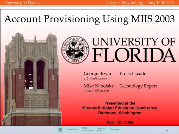
Provisioning Subscriber Services using AlliedView NMS. A set of high level slides to help you understand the iMAP features and how they are used to provision services using NMS. MPLS/IP Core Network. Video Conferencing. Streaming Server. PBX. PSTN/Mobile Gateway. iMG. VoIP

Provisioning Subscriber Services using AlliedView NMS
E N D
Presentation Transcript
Provisioning Subscriber Services using AlliedView NMS A set of high level slides to help you understand the iMAP features and how they are used to provision services using NMS
MPLS/IP Core Network Video Conferencing Streaming Server PBX PSTN/Mobile Gateway iMG VoIP Call Server Gaming Server Router Internet Intranet/VPN Service Provisioning & Network Management Network Management System Application Servers Services Services Service Provisioning &Network Management Business iMAP iMAP Broadband Services Router (BSR) Access Network Residential
TR101 Access Node “Level” iMAP 9400 iMAP 9700 iMG iMAP 9100
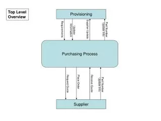
CPE, Access Node & Broadband Services Router Customer - name Location – address Connected to – port, chassis Central Fabric Controller (Aggregator) Port Line Card Service Provider 1 Service A - data Service B - voice Service Provider 2 Service X - data Service Y - voice Service Z - video Services – Data - Service Provider 1 Voice – Service Provider 2 Video – Service Provider 2 CPE Access Node Chassis
Splitter Ethernet Ethernet Ethernet Access in the Local Loop integrated Multi-service Access Platform Telephone iMAP VoIP Analog POTS Multiple Transmission media PBX E1/T1 E1/T1 TDM Leased Lines Any Service, Any Slot ADSL Modem Ethernet ADSL/ADSL2+ (ATM) Ethernet Network Port n x GbE or 10GbE Voice Data Video Ethernet Switch 24/56Gbps VDSL Modem Ethernet VDSL (ATM) Customer Ports SHDSL Modem Ethernet G.SHDSL (ATM) Ethernet FTTx Ethernet Ethernet Ethernet ONU Ethernet OLT EPON Transport Access Aggregation
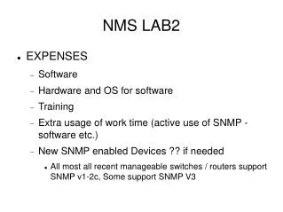
Summary of key NMS differentiators • Single screen for Multi-service Provisioning • Manages Network nodes (iMAP) + CPE (iMG + iBG) • Multi-services - VoIP POTS, E1/T1 lease lines, Multicast IPTV, High Speed Internet Access • Multiple media - copper twisted pairs and fibre (P2P & P2MP) • GbE & 10GbE Protected Transport Rings • XML/SOAP northbound interface • Subscriber Web Portal – self provisioning
Provisioning Services • “A ONE screen affair”
The Requirement – Deliver Multiple Services to a Subscriber via a single network connection Single Network Connection Service Provider 1 Service A - data Service B - voice Service Provider 2 Service X - data Service Y - voice Service Z - video Customer - name Location – address Connected to – port, chassis Services – Data - Service Provider 1 Voice – Service Provider 2 Video – Service Provider 2 Connecting Services to Subscribers …. Services are provisioned for delivery via an Ethernet access network
Triple Play Customer Form for RG 634 – Two Voice, Two Video, TLS, and Internet Access General Profile Transparent LAN Service Port Profile Internet Service Profile Video & Data Configuration Voice Profile for derived voice POTS port Profile POTS line Profile Voice Configuration
DSL Forum TR101 ArchitectureMigration to Ethernet-Based DSL Aggregation
TR101 - Migration to Ethernet-Based DSL Aggregation TR59 ATM to Ethernet ATM TR101
S - Tag Arrangements ATM Single - VC UniqueC -Tag Business or Common S-Tag Residential 1:1 N:1 VLAN - individual subscriber sessions are place d into a common VLAN based on service type TR-101 VLAN Architecture – ATM Single-VC Broadband Service Router (BSR) Home or Customer Premise Network Access Node NO S-Tag 101 Service 1 Service 1 102 Service 2 Service 2 Residential 101 Service 1 Service 1 Subscribers 102 Service 2 Service 2 (N:1) 101 Service 1 Service 1 xDSL Service X Service Y Layer2 Control Protocol (L2CP) Ethernet Priority C-Tagged Frames Ethernet Priority Double-Tagged Frames Ethernet Frames ATM Cells Ethernet Frames 1:1 VLAN – individual subscriber session is identified by a Q-in-Q double tag
Multi-ATM VC Access Architecture BPON OLT or Ethernet VLAN ATM VC
S - Tag Arrangements ATM Multiple - VCs Business or Residential 1:1 N:1 VLAN - individual subscriber sessions are place d into a common VLAN based on service type TR-101 VLAN Architecture – ATM multiple-VCs Broadband Service Router (BSR) Home or Customer Premise Network Access Node VC1 101 Service 1 Service 1 VC2 102 Service 2 Service 2 Residential 101 Service 1 NO S-Tag Subscribers Service 1 102 Service 2 Service 2 (N:1) 101 Service 1 Service 1 xDSL UniqueC -Tag Service X Common S-Tag Service Y Ethernet Priority Double-Tagged Frames Layer2 Control Protocol (L2CP) Ethernet Priority Tagged Frames Ethernet Frames ATM Cells Ethernet Frames 1:1 VLAN – individual subscriber session is identified by a Q-in-Q double tag
N:1 Shared VLANs Broadband Services Router ( BSR) Network bandwidth required is easily determined by knowing bandwidth needed per service. Largest user of bandwidth is multicast IPTV NetworkModules Voice Priority Video VLAN MAP & TRANSLATION VLAN MAP & TRANSLATION VLAN MAP & TRANSLATION VLAN MAP & TRANSLATION Service Modules Customer Y Customer X Customer Z
Video Video Video Voice Voice Voice Data Data Data N:1 Shared VLAN per service Application Services Access Network Aggregation and Transport Home Network Core Network Services Service ID = VLAN Network Access Node (xDSL) IPTV Video Broadband Services Router (BSR) Video Voice VoIP Telephony Core Network Data Access Network Internet Network Access Node (Ethernet) Service ID = IP Address Service ID = IP Address
Application Services Access Network Aggregation and Transport Core Network Home Network Services Data Data Data Data Data Data Data Data Data Voice Voice Voice Voice Voice Voice Voice Voice Voice Video Video Video Video Video Video Video Video Video 1 1 1 2 2 2 3 3 3 4 4 4 Aggregation M L K Video Conferencing Streaming Server DATA DATA DATA DATA DATA DATA DATA VOICE VOICE VOICE VOICE VOICE VOICE VOICE PSTN/Mobile Gateway VIDEO VIDEO VIDEO VIDEO VIDEO VIDEO VIDEO VoIP Call Server Gaming Server Internet Intranet/VPN Network Model - N:1 Shared VLAN per service Service VLANs = (data, voice, video) Line Card X PORT Line Card Y CFC PORT PORT Broadband Services Router (BSR) Line Card Z PORT Customer ID = slot.port.iMAP (DHCP Option 82) Service VLANs = (data, voice, video)
1:1 VLAN per subscriber per service Broadband Services Router ( BSR) Each VLAN identifies an IP flow to a subscriber. QoS of IP flow is managed dynamically by the Broadband Services Router NetworkModules Q-in-Q & VLAN MAP Data – Service Provider A Voice – Service Provider B VLAN MAP & TRANSLATION VLAN MAP & TRANSLATION VLAN MAP & TRANSLATION VLAN MAP & TRANSLATION Service Modules Customer Y Customer X Customer Z
Video Video Video Voice Voice Voice Data Data Data 1:1 VLAN per subscriber Application Services Access Network Aggregation and Transport Home Network Core Network Services C-VLAN = Customer port S-VLAN = Chassis IPTV Video Customer X Service Provider C Network Access Node (xDSL) C-VLAN +S-VLAN = Customer ID VoIP Telephony Internet Broadband Services Router (BSR) Customer Y IPTV Video Customer X Customer Y Service Provider B Core Network VoIP Telephony Customer Y Access Network Internet Customer Z IPTV Video Network Access Node (Ethernet) Service Provider A VoIP Telephony Service ID = IP Address Service ID = IP Address Internet
Application Services Access Network Aggregation and Transport Core Network Home Network Services Data Data Data Data Data Data Data Data Data Voice Voice Voice Voice Voice Voice Voice Voice Voice Video Video Video Video Video Video Video Video Video 1 1 1 2 2 2 3 3 3 4 4 4 Aggregation M K L Video Conferencing C-VLAN Streaming Server C-VLAN C-VLAN C-VLAN PSTN/Mobile Gateway C-VLAN VoIP Call Server Gaming Server S-VLAN Internet Intranet/VPN Network Model - 1:1 VLAN per subscriber Customer ID = PORT + Node ID = C-VLAN + S–VLAN Line Card X C-VLAN C-VLAN Customerto Service Mapping C-VLAN Line Card Y C-VLAN C-VLAN CFC S-VLAMN = Node ID + Service Provider ID C-VLAN C-VLAN C-VLAN Broadband Services Router (BSR) C-VLAN C-VLAN C-VLAN Line Card Z C-VLAN C-VLAN Customer PORT = C-VLAN C-VLAN
Hybrid – VLAN per service & VLAN per subscriber Broadband Services Router ( BSR) Additional Bandwidth determined dynamically by the admission of each new application stream Multicast IPTV service. Bandwidth determined by number of TV channels NetworkModules Q-in-Q & VLAN TRANSLATION Video – Service Provider A Voice – Service Provider B Data – Service Provider C VLAN TRANSLATION VLAN TRANSLATION VLAN TRANSLATION VLAN TRANSLATION Service Modules Customer Y Customer X Customer Z
Access Node Control Protocol (ANCP) Broadband Services Router needs to know the bandwidth currently being used by the subscriber in order to manage QoS of IP flows and Call Admission Control (CAC) Broadband Services Router ( BSR) Access Node Control Protocol (ANCP) CONTROL PLANE NetworkModules Q-in-Q & VLAN TRANSLATION Video – Service Provider A Voice – Service Provider B Data – Service Provider C VLAN MAP & TRANSLATION VLAN MAP & TRANSLATION VLAN MAP & TRANSLATION VLAN MAP & TRANSLATION Service Modules Customer Y Customer X Customer Z
EtherType Access Architecture Single ATM VC used for all services
1:1 + N:1 Service Mapping in an EtherType Access Architecture
EtherType Access with Dual GE Uplinks and 1:1 VLANs for Internet Access
Physical Port-Based Traffic Mapping with Multi-VC Access Architecture
Physical Port-Based Traffic Mapping with Multi-VLAN Access Architecture
NAT/Layer 3 Functionality in the Home Gateway: Multi-VC Access Architecture
NAT/Layer 3 Functionality in the Home Gateway: EtherType Access Architecture
EtherType (2 bytes) Source MAC Address (6 bytes) Destination MAC Address (6 bytes) CRC Payload MAC Header (14 bytes) DATA (46-1500 bytes) (4 bytes) Ethernet Type II Frame (64 to 1518 bytes) The most common Ethernet Frame format, Type II
1518 4 2 2 2 2 6 2 6 46 - 1500 Ethernet Frame Formats
Provisioning multiple services to subscribers Requirement Customer, service, location Service Provider, Service IP Address Chassis, card, port MPLS LSP VLAN Service Provider C DATA PORT VOICE DATA VIDEO Customer X PORT VOICE VIDEO DATA Service Provider B DATA DATA PORT PORT VOICE PORT VOICE VOICE VIDEO VIDEO VIDEO DATA Access Core Customer Y Service Provider A PORT VOICE DATA PORT VIDEO VOICE VIDEO S-VLAN C-VLAN Q-in-Q … … Access TAG2 DA SA Len / EType IP Packet TAG1 FCS ... Core Layer 2 Header IP Packet MPLS header MPLS header
802.1p – C-VLAN Priority Classify & Mark 802.1p – S-VLAN Priority Call Admision Control (CAC) & Policy Server S-VLAN C-VLAN Q-in-Q … … Map IP Flows to CoS Access VLAN ID2 DA SA Len / EType IP Packet VLAN ID1 FCS PRIORITY PRIORITY LSPs are traffic engineered to support QoS for application + ANCP Classify IP flows & select LSP MPLS Class-of-Service ... MPLS header Layer 2 Header IP Packet BSR Class-of-Service (CoS) LABEL S TTL MPLS header DSCP IP DiffServ Field IP Header DiffServ Field …… …… APPLICATION DATA Service IP SA IP DA Application IP flow Managing the attributes of Services
Strict Priority Best-Effort Better-than-BE Broadcast TV Scheduler Hierarchal Scheduling (HS) within a Broadband Service Router Home 1 Queues Home 1 Queues Business Queues Multicast IPTV IP Queues Subscriber queues per service Shape and police each service IP/VLAN Node Per DSLAM port Shape and police each subscriber VLAN Per DSLAM scheduler (if required) DSLAM Y DSLAM 1 DSLAM X Limit traffic and provide fairness per IP DSLAM Broadband Service Router (BSR) GbE To IP DSLAM Layer2 Control Protocol (L2CP) iMG
Adds the Remote Agent ID (iMAP shelf), Circuit ID (slot.port, and VID) & Vendor-Class ID (RGType) DHCP Relay Option 82/60 DHCP Server BOOT VLAN (untagged) DHCP DISCOVERY 1 POWER Authenticates IP address for iMG + IP Address of tftp server 2 BOOTSTRAP location & directory per RGType + RGManagement VLAN tftp REQUEST BOOT CODE (MD5SUM file) Adds the Remote Agent ID (iMAP shelf), Circuit ID (slot.port, and VID) & Vendor-Class ID (RGType) tftp server Boot code for RGType 3 REBOOT, DHCP DISCOVERY DHCP Requests new IP address 4 5 6 RGManagement VLAN RGMgmt IP address Telnet & CLI Downloads operational configuration, saves and reboots iMG 7 8 IN SERVICES Auto Provisioning a subscriber with Services Listener Learns RGMgmt IP address
iMG Auto Configuration via AlliedView NMS DHCP Server (Option 82/60 support) 2. DHCP server provides to RG: - its IP address and also the - IP address of the tftp server (NMS) - “bootstrap” directory (per RG type)at tftp server 6. Use DHCP Listener to Discover RG Mgmt IP address. DHCP Server “Listener” 6 NMS iMAP’s DHCP Relay configured to send DHCP to both Server and Listener Via MAPMgmt VLAN 7 5 2 7. NMS configures RG using RGMgmt IP address and RGMgmt VLAN DHCP Relay 8 tftp Server (usually resides on NMS also) 3 8. RG gets configuration,,saves and reboots and provides requested services. 4 1 RGMgmt VLAN 3. RG loads “bootstrap” file from tftp server into Flash and reboots Bootstrap VLAN 5. DHCP server provides new “RGMgmt” IP address to RG 1. RG Asks for DHCP Address over Bootstrap VLAN 4. RG reboots using the RGMgmt VLAN. Requests new IP address to DHCP Server Residential Gateway
Thank You dick_willson@alliedtelesis.com Visit us online at www.alliedtelesis.com