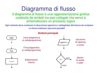
Download

1 / 100
1.01k likes | 1.18k Vues
Introduzione al Flusso di Progetto di Circuiti e Sistemi Digitali. Cristina Silvano CEFRIEL - Politecnico di Milano Electronic Design Automation (EDA) Area Via Fucini 2, I-20133 Milano (Italy) Ph.: +39-2-23954-325 Fax: +39-2-23954-254 e-mail: silvano@cefriel.it. Sommario. Introduzione

E N D
Introduzione al Flusso di Progetto di Circuiti e Sistemi Digitali Cristina Silvano CEFRIEL - Politecnico di Milano Electronic Design Automation (EDA) Area Via Fucini 2, I-20133 Milano (Italy) Ph.: +39-2-23954-325 Fax: +39-2-23954-254 e-mail: silvano@cefriel.it Cristina Silvano - CEFRIEL
Sommario • Introduzione • Evoluzione tecnologica • Progettazione di circuiti full-custom e semi-custom • Flusso di progetto • Livelli di astrazione • Programma del corso e modalità di esame Cristina Silvano - CEFRIEL
Introduzione • La tecnologia microelettronica, basata sull’utilizzo dei semiconduttori, ha subito un’enorme evoluzione negli ultimi decenni. • I circuiti VLSI (Very Large Scale Integration) costituiscono la tecnologia strategica per lo sviluppo dei sistemi digitali. • Principali settori di mercato: • Sistemi di elaborazione • Telecomunicazioni • Elettronica di consumo • Automotive • Automazione • Il continuo incremento del livello di integrazione dei dispositivi microelettronici ha permesso la realizzazione di sistemi di complessità crescente. Cristina Silvano - CEFRIEL
Introduzione (cont.) • L’elevato livello di integrazione implica: • Raggiungimento di prestazioni sempre più spinte • Riduzione dei costi • Aumento dell’affidabilità • Analisi valida nell’ipotesi che i volumi di vendita del circuito siano abbastanza elevati da recuperare i costi di progetto e di fabbricazione.Esempio: microprocessori general-purpose. • L’impiego di uno stile di progetto (full-custom o semi-custom) dipende principalmente dai volumi di vendita previsti per il circuito. • Alcune applicazioni richiedono circuiti integrati dedicati o ASIC (Application Specific Integrated Circuit) non prodotti in alti volumi poiché specializzati a compiere un limitato insieme di operazioni. Cristina Silvano - CEFRIEL
Introduzione (cont.) • La rapida evoluzione tecnologica del mercato microelettronico rende un circuito rapidamente obsoleto. • Riduzione del time-to-market di un circuito o sistema digitale Riduzione dei tempi di sviluppo. • Aumento del livello di qualità e affidabilità richiesto al prodotto. Cristina Silvano - CEFRIEL
Introduzione (cont.) • Principali requisiti del mercato: • Livello di integrazione • Complessità progettuale • Prestazioni • Dissipazione di potenza • Affidabilità • Time-to-market • Costi • Volumi di produzione • Importanza strategica delle metodologie e dei tool CAD (Computer Aided Design) per raggiungere gli obiettivi di progetto nel rispetto dei tempi di sviluppo. Cristina Silvano - CEFRIEL
Mercato mondiale dei semiconduttori Mercato mondiale dei semiconduttori Cristina Silvano - CEFRIEL
Mercato mondiale del CAD elettronico Cristina Silvano - CEFRIEL
Tipologia dei progetti microelettronici Cristina Silvano - CEFRIEL
Principali trend dell’industria microelettronica • Miglioramenti tecnologici • Riduzioni dell’area di silicio • Maggiori prestazioni • Maggior numero di transistor su un singolo chip • Maggiore livello di integrazione • Maggiore complessità dei sistemi • Riduzione dei costi • Maggiore affidabilità Cristina Silvano - CEFRIEL
Capacità chip DRAM Densità della Logica nei Microprocessori DRAM Year Size 1980 64 Kb 1983 256 Kb 1986 1 Mb 1989 4 Mb 1992 16 Mb 1996 64 Mb 1999 256 Mb 2002 1 Gb Evoluzione Tecnologica Cristina Silvano - CEFRIEL
Evoluzione Tecnologica • Processori • Densità: circa 30% per anno • Freq. Clock: circa 20% per anno • Memorie DRAM • Capacità: circa 60% per anno (4x ogni 3 anni) • Cycle Time: circa 10% per anno • Costo per bit: circa 25% per anno • Dischi • Capacità attuale: circa 60% per anno (4x ogni 3 anni) • Capacità (prima del 1990): circa 25% per anno (2x ogni 3 anni) • Tempo di accesso: circa 10% per anno • Tecnologia VLSI: 1.2 x 1.2 x 1.2 = 1.7 x /anno (5x ogni 3 anni) • Lunghezza del canale: circa 10% per anno vel. 1.2x /anno • Densità: circa 1.2 x/anno • Area: circa 1.2 x/anno Cristina Silvano - CEFRIEL
Evoluzione delle Prestazioni Supercomputers Mainframes Minicomputers Log of Performance Microprocessors Y ear 1970 1975 1980 1985 1990 1995 Cristina Silvano - CEFRIEL
Evoluzione delle Prestazioni dei Processori (SPEC) • Attualmente le prestazioni aumentano di circa 60% per anno (2x ogni 1.5 anni) RISC introduction Cristina Silvano - CEFRIEL
Evoluzione delle tecnologie CMOS • Nuovi processi CMOS a 0.25 m e 0.18 m. Cristina Silvano - CEFRIEL
Tecnologie di Memoria • Random Access: • “Random” : stesso tempo di accesso per tutte le locazioni • DRAM: Dynamic Random Access Memory • Alta densità, bassa dissipazione di potenza, basso costo, basse prestazioni • Dynamic: necessita periodicamente di “refresh” • SRAM: Static Random Access Memory • Bassa densità, alta dissipazione di potenza, costose, alte prestazioni • Static: il contenuto viene mantenuto • Memoria Principale: DRAMs + Cache: SRAMs • “Non-so-random” Access Technology: • Tempo di accesso variabile da locazione a locazione. • Esempi: Dischi, CDROM • Sequential Access Technology: • Tempo di accesso lineare con la locazione. • Esempio: Tape Cristina Silvano - CEFRIEL
DRAM vs. SRAM • Capacità: DRAM circa 4 8 volte maggiore SRAM • Prestazioni: SRAM circa 8 16 volte più veloci DRAM • Costo: SRAM circa 8 16 volte più costose DRAM Cristina Silvano - CEFRIEL
Evoluzione delle prestazioni delle DRAM • Una nuova generazione (4x) ogni 3 anni (circa 60% per anno) • Le prestazioni migliorano più lentamente: cycle time migliora circa del 22% per generazione (circa 7% per anno) Cristina Silvano - CEFRIEL
DRAM Year Size Cycle Time 1980 64 Kb 250 ns 1983 256 Kb 220 ns 1986 1 Mb 190 ns 1989 4 Mb 165 ns 1992 16 Mb 145 ns 1995 64 Mb 120 ns 1000:1! 2:1! Evoluzione Tecnologica Capacità Velocità (latenza) Logica: 2x in 3 anni 2x in 3 anni DRAM: 4x in 3 anni 2x in 10 anni Dischi: 4x in 3 anni 2x in 10 anni Cristina Silvano - CEFRIEL
µProc 60%/yr. (2X/1.5yr) 1000 CPU “Moore’s Law” 100 Processor-Memory Performance Gap:(grows 50% / year) Performance 10 DRAM 9%/yr. (2X/10 yrs) DRAM 1 1980 1981 1982 1983 1984 1985 1986 1987 1988 1989 1990 1991 1992 1993 1994 1995 1996 1997 1998 1999 2000 Time Processor-DRAM Gap Cristina Silvano - CEFRIEL
Processor-DRAM Gap • Ricorso alle memorie cache per colmare il gap • Processor-DRAM performance gap • Tempo richiesto da un cache miss espresso in numero di instruzioni 1st Alpha (7000): 340 ns/5.0 ns = 68 clks x 2 or 136 instruzioni 2nd Alpha (8400): 266 ns/3.3 ns = 80 clks x 4 or 320 instruzioni 3rd Alpha (t.b.d.): 180 ns/1.7 ns =108 clks x 6 or 648 instruzioni • 1/2X latency x 3X clock rate x 3X instr/clock 5X Cristina Silvano - CEFRIEL
Memory Hierarchy • By taking advantage of the principle of locality: • Present the user with as much memory as is available in the cheapest technology. • Provide access at the speed offered by the fastest technology. Processor Control Tertiary Storage (Disk) Secondary Storage (Disk) Second Level Cache (SRAM) Main Memory (DRAM) Datapath On-Chip Cache Registers 10,000,000,000s (10s sec) 10,000,000s (10s ms) 1s Speed (ns): 10s 100s Size (bytes): 100s Ms Ks Ts Gs Cristina Silvano - CEFRIEL
Cycle Time Access Time Time Main Memory Background • Performance of Main Memory: • Latency: Cache Miss Penalty • Access Time: time between request and word arrives • Cycle Time: time between requests • Bandwidth: I/O & Large Block Miss Penalty (L2) • Main Memory is DRAM: Dynamic Random Access Memory • Dynamic since needs to be refreshed periodically (8 ms) • Addresses divided into 2 halves (Memory as a 2D matrix): • RAS or Row Access Strobe • CAS or Column Access Strobe • Cache uses SRAM: Static Random Access Memory • No refresh (6 transistors/bit vs. 1 transistor) Size: DRAM/SRAM 4-8, Cost/Cycle time: SRAM/DRAM 8-16 • DRAM (Read/Write) Cycle Time >> DRAM (Read/Write) Access Time Cristina Silvano - CEFRIEL
DRAM Generation ‘86 ‘89 ‘92 ‘96 ‘99 ‘02 1 Mb 4 Mb 16 Mb 64 Mb 256 Mb 1 Gb 32 8 Memory per DRAM growth @ 60% / year 4 MB 8 MB 16 MB 32 MB 64 MB 128 MB 256 MB 16 4 8 2 Minimum PC Memory Size 4 1 Memory per System growth @ 25%-30% / year 8 2 4 1 8 2 Fewer DRAMs/System over Time (from Pete MacWilliams, Intel) Cristina Silvano - CEFRIEL
DRAM • DRAMs: capacity +60%/yr, cost –30%/yr • 2.5X cells/area, 1.5X die size in 3 years • ‘97 DRAM fab line costs $1B to $2B • DRAM only: density, leakage v. speed • Rely on increasing no. of computers & memory per computer (60% market) • SIMM or DIMM is replaceable unit => computers use any generation DRAM • Commodity, second source industry => high volume, low profit, conservative • Little organization innovation in 20 years page mode, EDO, Synch DRAM • Order of importance: 1) Cost/bit 2) Capacity Cristina Silvano - CEFRIEL
Gestione delle istruzioni nei processori F D E F D E F D E Istruzione 1 Istruzione 2 Istruzione 3 Tempo Gestione sequenziale delle istruzioni F D E Istruzione 1 F = Fetch o prelievo dell’istruzioneD = Decodifica E = Esecuzione F D E Istruzione 2 F D E Istruzione 3 Tempo Gestione delle istruzioni di tipo pipeline a tre stadi Cristina Silvano - CEFRIEL
F D A R E W Istruzione 1 F D A R E W Istruzione 2 F D A R E W Istruzione 3 F D A R E W F = Fetch o prelievo dell’istruzioneD = Decodifica A = Calcolo indirizzoR = Lettura operandiE =EsecuzioneW = Scrittura risultato Istruzione 4 F D A R E W Istruzione 5 F D A R E W Istruzione 6 Tempo Gestione delle istruzioni nei processori Gestione delle istruzioni di tipo pipeline a sei stadi Cristina Silvano - CEFRIEL
Istruzione 1Istruzione 2 F D A R E W F D A R E W Istruzione 3Istruzione 4 F D A R E W F D A R E W Istruzione 5Istruzione 6 F D A R E W F D A R E W Istruzione 7Istruzione 8 F D A R E W F D A R E W Istruzione 9Istruzione 10 F D A R E W F D A R E W Istruzione 11Istruzione 12 F D A R E W F D A R E W Tempo Gestione delle istruzioni nei processori Gestione delle istruzioni di tipo pipeline superscalare a sei stadi Cristina Silvano - CEFRIEL
Caratteristiche dei principali processori Intel e Motorola Cristina Silvano - CEFRIEL
Caratteristiche processori PowerPC601 e Intel Pentium Cristina Silvano - CEFRIEL
Caratteristiche processori di ultima generazione Cristina Silvano - CEFRIEL
MadisonIA-64 ... DeerfieldIA-64 McKinley ... Performance FutureIA-32 ... Merced Foster Cascades Tanner Pentium IIXeon ‘98.25 m ‘99 ‘00.18 m ‘01 ‘02.13 m Intel Processors Roadmap ... Cristina Silvano - CEFRIEL
MBus Module SuperSPARC Floating-point Unit DRAM Controller CC L2 Integer Unit MBus MBus control M-S Adapter L64852 Inst Cache Ref MMU Data Cache STDIO SBus serial kbd SCSI Store Buffer SBus DMA mouse Ethernet audio RTC Bus Interface SBus Cards Floppy Esempio di architettura di un calcolatore • TI SuperSPARCtm TMS390Z50 in Sun SPARCstation 20 Boot PROM Cristina Silvano - CEFRIEL
Computer Workstation Design Target: 25% of cost on processor 25% of cost on memory (minimum memory size) Rest on I/O devices, power supplies, box Processor Memory Devices Control Input Datapath Output Levels of Organization of SPARCstation 20 Cristina Silvano - CEFRIEL
Memory SIMMs Memory Controller SIMM Bus MBus Disk MBus Slot 1 SBus Slot 1 SBus Slot 3 Tape MBus Slot 0 SBus Slot 0 SBus Slot 2 SCSI Bus MSBI SEC MACIO SBus Keyboard Floppy External Bus & Mouse Disk The SPARCstation 20 Cristina Silvano - CEFRIEL
SIMM Bus Memory Controller Standard I/O Bus: SCSI Bus Processor/Mem Bus: MBus Sun’s High Speed I/O Bus: SBus MSBI SEC MACIO Low Speed I/O Bus: External Bus The Underlying Interconnect of SPARCstation 20 Cristina Silvano - CEFRIEL
MBus Slot 1 MBus Slot 0 Processor and Caches of SPARCstation 20 MBus Module Processor MBus Registers Datapath Internal Cache Control External Cache Cristina Silvano - CEFRIEL
SIMM Slot 0 SIMM Slot 1 SIMM Slot 2 SIMM Slot 3 SIMM Slot 4 SIMM Slot 5 SIMM Slot 6 SIMM Slot 7 DRAM DRAM DRAM DRAM DRAM DRAM DRAM DRAM DRAM DRAM Memory of SPARCstation 20 Memory SIMM Bus Memory Controller DRAM SIMM Cristina Silvano - CEFRIEL
Basic Technology: CMOS • CMOS: Complementary Metal Oxide Semiconductor • NMOS (N-Type Metal Oxide Semiconductor) transistors • PMOS (P-Type Metal Oxide Semiconductor) transistors • NMOS Transistor • Apply a HIGH (Vdd) to its gateturns the transistor into a “conductor” • Apply a LOW (GND) to its gateshuts off the conduction path • PMOS Transistor • Apply a HIGH (Vdd) to its gate shuts off the conduction path • Apply a LOW (GND) to its gate turns the transistor into a “conductor” Vdd = 5V GND = 0v Vdd = 5V GND = 0v Cristina Silvano - CEFRIEL
Open Charge Out Open Discharge Basic Components: CMOS Inverter Vdd Circuit Symbol • Inverter Operation PMOS In Out In Out NMOS Vout Vdd Vdd Vdd Vdd Vin Vdd Cristina Silvano - CEFRIEL
A B Out A B Out A Out 0 0 1 A Out 0 0 1 0 1 1 0 1 0 B B 1 0 1 1 0 0 1 1 0 1 1 0 Vdd Vdd A Out B B Out A Basic Components: CMOS Logic Gates NOR Gate NAND Gate Cristina Silvano - CEFRIEL
Vdd Vdd A Out B B Out A Gate Comparison • If PMOS transistors is faster: • It is OK to have PMOS transistors in series • NOR gate is preferred • NOR gate is preferred also if H -> L is more critical than L -> H • If NMOS transistors is faster: • It is OK to have NMOS transistors in series • NAND gate is preferred • NAND gate is preferred also if L -> H is more critical than H -> L NOR Gate NAND Gate Cristina Silvano - CEFRIEL
In Out Ideal (CS) versus Reality (EE) • When input 0 -> 1, output 1 -> 0 but NOT instantly • Output goes 1 -> 0: output voltage goes from Vdd (5v) to 0v • When input 1 -> 0, output 0 -> 1 but NOT instantly • Output goes 0 -> 1: output voltage goes from 0v to Vdd (5v) • Voltage does not like to change instantaneously Voltage Vout 1 => Vdd Vin 0 => GND Time Cristina Silvano - CEFRIEL
Fluid Timing Model Level (V) = Vdd Vdd • Water <-> Electrical Charge Tank Capacity <-> Capacitance (C) • Water Level <-> Voltage Water Flow <-> Charge Flowing (Current) • Size of Pipes <-> Strength of Transistors (G) • Time to fill up the tank ~ C / G Tank Level (Vout) SW1 SW1 SW2 Sea Level (GND) Vout Cout SW2 Reservoir Tank (Cout) Bottomless Sea Cristina Silvano - CEFRIEL
Vdd Vin V1 Vout Vout Cout Voltage Vdd V1 Vout Vin Vdd/2 d1 d2 GND Series Connection Vdd • Total Propagation Delay = Sum of individual delays = d1 + d2 • Capacitance C1 has two components: • Capacitance of the wire connecting the two gates • Input capacitance of the second inverter Vin V1 G1 G2 G1 G2 C1 Time Cristina Silvano - CEFRIEL
Review: Calculating Delays Vdd Vdd Vin V1 V2 • Sum delays along serial paths • Delay (Vin -> V2) ! = Delay (Vin -> V3) • Delay (Vin -> V2) = Delay (Vin -> V1) + Delay (V1 -> V2) • Delay (Vin -> V3) = Delay (Vin -> V1) + Delay (V1 -> V3) • Critical Path = The longest among the N parallel paths • C1 = Wire C + Cin of Gate 2 + Cin of Gate 3 Vin V1 V2 G1 G2 C1 V3 Vdd V3 G3 Cristina Silvano - CEFRIEL
Vout Delay Va -> Vout X A B Combinational Logic Cell . . . Cout X X X X X delay per unit load X Internal Delay Ccritical Cout Review: General C/L Cell Delay Model • Combinational Cell (symbol) is fully specified by: • functional (input -> output) behavior • truth-table, logic equation, VHDL • load factor of each input • critical propagation delay from each input to each output for each transition • THL(A, o) = Fixed Internal Delay + Load-dependent-delay x load Cristina Silvano - CEFRIEL
Static RAM Cell 6-Transistor SRAM Cell word word (row select) • Write: 1. Drive bit lines (bit=1, bit=0) 2.. Select row • Read: 1. Precharge bit and bit to Vdd 2.. Select row 3. Cell pulls one line low 4. Sense amp on column detects difference between bit and bit 0 1 0 1 bit bit bit bit replaced with pullup to save area Cristina Silvano - CEFRIEL
Din 3 Din 2 Din 1 Din 0 WrEn Precharge Wr Driver & Precharger Wr Driver & Precharger Wr Driver & Precharger Wr Driver & Precharger - + - + - + - + A0 Word 0 SRAM Cell SRAM Cell SRAM Cell SRAM Cell A1 Address Decoder A2 Word 1 SRAM Cell SRAM Cell SRAM Cell SRAM Cell A3 : : : : Word 15 SRAM Cell SRAM Cell SRAM Cell SRAM Cell - + - + - + - + Sense Amp Sense Amp Sense Amp Sense Amp Dout 2 Dout 1 Dout 0 Dout 3 Typical SRAM Organization: 16-word x 4-bit Cristina Silvano - CEFRIEL
1-Transistor Memory Cell (DRAM) • Write: • 1. Drive bit line • 2.. Select row • Read: • 1. Precharge bit line to Vdd • 2.. Select row • 3. Cell and bit line share charges • Very small voltage changes on the bit line • 4. Sense (fancy sense amp) • Can detect changes of ~1 million electrons • 5. Write: restore the value • Refresh • 1. Just do a dummy read to every cell. row select bit Cristina Silvano - CEFRIEL