Download
1 / 1
10 likes | 101 Vues
Explore the use of JMAG software to accurately model and analyze the performance of a linear induction motor (LIM) in 2D and 3D, compare simulation results with lab measurements, and enhance understanding of motor design. Gain insights into Maxwell's equations, Faraday's law, Ampere's law, and Gauss's law for magnetism to optimize LIM performance. Anticipate promising results that bridge theoretical simulation and practical testing. Acknowledging the support from the PURE program by Rockwell Collins.

E N D
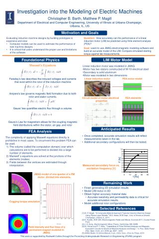
Investigation into the Modeling of Electric Machines Christopher B. Barth, Matthew P. Magill Department of Electrical and Computer Engineering, University of Illinois at Urbana-Champaign, Urbana, IL, US Motivation and Goals • Evaluating induction machine designs by building prototypes is expensive and slow • Computer models can be used to estimate the performance of new machine designs • It is critical that users understand the proper use and limitations of the software • Question:How accurately can the performance of a linear induction motor (LIM) be predicted using finite element analysis (FEA)? • Goal: Learn to use JMAG electromagnetic modeling software and build an accurate model of the LIM. Compare simulated starting torque against lab measurements. Foundational Physics LIM Motor Model • Maxwell’s Equations • Linear induction motor was modeled in JMAG • Motor has two stators constructed of M-19 electrical steel • Secondary is solid aluminum • Motor was modeled in two dimensions Linear induction motor FEA motor model • Faraday’s law describes the induced voltages and currents that exist within the rotor of the induction machine • Ampere’s law governs magnetic field formation due to both rotor and stator currents. Circuit model of motor electrical properties FEA elements • Gauss’ law quantifies electric flux through a volume. • Gauss’s Law for magnetism allows for the coupling magnetic field distributions within the stator, air gap, and rotor Anticipated Results FEA Analysis • Once completed, accurate simulation results will reflect measurements taken in the lab. • Additional secondary configurations will then be tested. The complexity of applying Maxwell equations directly is prohibitive in most cases. To circumvent this problem FEA can be used. • The volume (called the computation domain) over which calculations are to be performed is divided into a large number of elements. • Maxwell’s equations are solved at the junctions of the elements (nodes). • Fields between the vertices are estimated through interpolation. F [N] Measured secondary force vs. excitation frequency [1] JMAG model of one quarter of a PM motor divided into elements. f [Hz] Remaining Work • Finish generating 2D simulation results • Model LIM motor in 3D • Obtain higher accuracy material data • Accurate resistivity and permeability data is critical for accurate simulation results. • Model additional rotor configurations Cogging torque simulation Selected References • [1] M. P. Magill, “A Composite Material Approach Towards Induction Machine Design Using Planar Layer Models,” M.S. thesis, ECE Dept., Univ. of Illinois at Urbana-Champaign, Urbana, IL, 2011. • [2] E. Kudeki, ECE 329: Electromagnetic Fields and Waves. Summer 2011. Course Power Point. • [3] J. A. Kong, Electromagnetic Wave Theory, Cambridge, MA: EMW. • [4] M. Yilmaz and P. T. Krein, “Capabilities of Finite Element Analysis and Magnetic Equivalent Circuits for Electrical Machine Analysis and Design,” in Proc. IEEE Power Elec. Spec. Conf., Jun. 2008, pp. 4027 - 4033. • [5] JMAG Studio 10 Online Manual, 9 ed., JSOL Corp., Chuo-ku Tokyo, 2010 Field intensity and flux lines of a permanent magnet modeled in JMAG. • This work is supported by Rockwell Collins through the Promoting Undergraduate Research in Engineering (PURE) program