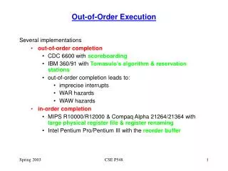
In-Order Execution
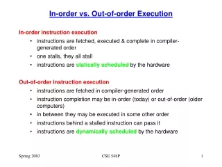
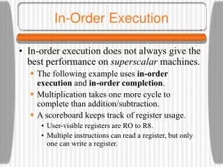
In-Order Execution. In-order execution does not always give the best performance on superscalar machines. The following example uses in-order execution and in-order completion . Multiplication takes one more cycle to complete than addition/subtraction.

In-Order Execution
E N D
Presentation Transcript
In-Order Execution • In-order execution does not always give the best performance on superscalar machines. • The following example uses in-order execution and in-order completion. • Multiplication takes one more cycle to complete than addition/subtraction. • A scoreboard keeps track of register usage. • User-visible registers are RO to R8. • Multiple instructions can read a register, but only one can write a register.
In-Order Execution • The scoreboard has a small counter for each register telling how many times that register is in use by currently-executing instructions. • If a maximum of, say, 15 instructions may be executing at once, then a 4-bit counter will do. • The scoreboard also has a counter to keep track of registers being used as destinations. • Since only one write at a time is allowed, these registers can be 1-bit wide. • In a real machine, the scoreboard also keeps track of functional unit usage.
In-Order Execution • We can notice three kinds of dependencies which can cause problems (instruction stalls): • RAW (Read After Write) dependence • WAR (Write After Read) dependence • WAW (Write After Write) dependence • In a WAR dependence, one instruction is trying to overwrite a register that a previous instruction may not yet have finished reading. A WAW dependence is similar.
In-Order Execution • In-order completion is important as well in order to have the property of precise interrupts. • Out-of-order completion leads to imprecise interrupts (we don’t know what has completed at the time of an interrupt - this is not good). • In order to avoid stalls, let us now permit out-of-order execution and out-of-order retirement.
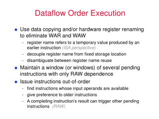
Out-of-Order Execution • The previous example also introduces a new technique called register renaming. • The decode unit has changed the use of R1 in I6 and I7 to a secret register, S1, not visible to the programmer. • Now I6 can be issued concurrently with I5. • Modern CPUs often have dozens of secret registers for use with register renaming. • This can often eliminate WAR and WAW dependencies.
Speculative Execution • Computer programs can be broken up into basic blocks, with each basic block consisting of a linear sequence of code with one entry point and one exit. • A basic block does not contain any control structures. • Therefore its machine language translation does not contain any branches. • Basic blocks are connected by control statements. Programs in this form can be represented by directed graphs.
Speculative Execution • Within each basic block, the reordering techniques seen work well. • Unfortunately, most basic blocks are short and there is insufficient parallelism to exploit. • The next step is to allow reordering to cross block boundaries. • The biggest gains come when a potentially slow operation can be moved upward in the graph to get it going earlier. Moving code upward over a branch is called hoisting.
Speculative Execution • Imagine that all of the variables of the previous example except evensum and oddsum are kept in registers. • It might make sense to move their LOAD instructions to the top of the loop, before computing k, to get them started early on, so the values will be available when they are needed. • Of course only one of them will be needed on each iteration, so the other LOAD will be wasted.
Speculative Execution • Speculative execution introduces some interesting problems. • It is essential that none of the speculative instructions have irrevocable results because it may turn out later that they should not have been executed. • One way to do this is to rename all the destination registers to be used by speculative code. In this way, only scratch registers are modified.
Speculative Execution • Another problem arises if a speculatively executed instruction causes an exception. • A LOAD instruction may cause a cache miss on a machine with a large cache line and a memory far slower than the CPU and cache. • One solution is to have a special SPECULATIVE-LOAD instruction that tries to fetch the word from the cache, but if it is not there, just gives up.
Speculative Execution • A worse situation happens with the following statement: if (x > 0) z = y/x; • Suppose that the variables are all fetched into registers in advance and that the (slow) floating-point division is hoisted above the if test. • If x is 0, the resulting divide-by-zero trap terminates the program even though the programmer has put in explicit code to prevent this situation. • One solution is to have special versions of instructions that might cause exceptions.
Pentium II Microarchitecure • Known as the P6 microarchitecture • The Pentium II supports 32-bit operands and arithmetic as well as 64-bit floating point operations. • It also supports 8- and 16-bit operands and operations as a legacy from earlier processors in the family. • It can address up to 64 GB of memory and it reads words from memory 64 bits at a time. • The Pentium II SEC package contains two ICs: the CPU and the unified level 2 cache.
Pentium II Microarchitecure • There are three primary components of the CPU: • Fetch/Decode unit • Dispatch/Execute unit • Retire unit • Together they act as a high-level pipeline. • The units communicate through an instruction pool. • The ROB (ReOrder Buffer) is a table which stores information about partially completed instructions.
Pentium II Microarchitecure • The Fetch/Decode unit fetches the instructions and breaks them into micro-operations for storage in the ROB. • The Dispatch/Execute unit takes micro-operations from the ROB and executes them. • The Retire unit completes execution of each micro-operation and updates the registers. • Instructions enter the ROB in order, can be executed out of order, but are retired in order again.
The Fetch/Decode Unit • The Fetch/Decode unit is highly pipelined, with seven stages. • Instructions enter the pipeline in stage IFU0, where entire 32-byte lines are loaded from the I-cache. • Since the IA-32 instruction set has variable-length instructions with many formats, IFU1 analyzes the byte stream to locate the start of each instruction. • IFU2 aligns the instructions so the next stage can decode them easily. • Decoding starts in ID0. Each IA-32 instruction is broken up into one or more micro-operations. Simple instructions may require just 1 micro-op.
The Fetch/Decode Unit • The micro-operations are queued in stage ID1. This stage also does branch prediction. • The static predictor predicts backward branches to be taken and forward ones not to be. After that, the dynamic branch predictor uses a 4-bit history-based algorithm. If the branch is not in the history table, the static prediction is used. • To avoid WAR and WAW dependencies, the Pentium II supports register renaming using one of 40 internal scratch registers. This is done in the RAT stage. • Finally, the micro-operations are deposited in the ROB three per clock-cycle. The micro-op will be issued when all required resources are ready.
The Dispatch Execute Unit • The Dispatch/Execute unit schedules and executes the micro-operations, resolving dependencies and resource conflicts. • Although only three ISA instructions can be decoded per clock cycle (in ID0) as many as five micro-operations can be issued for execution in one clock cycle, one on each port. • A complex scoreboard keeps track of resources. • Some execution units share a single port. • The Reservation Station is a 20-entry queue.
The Retire Unit • Once a micro-operation has been executed, it goes back to the Reservation Station and then to the ROB to await retirement. • The Retire unit is responsible for sending the results to the appropriate place - the correct register. • If a speculatively executed instruction needs to be rolled back, it is done here (its results are discarded).
Microarchitecture of the Pentium 4 • The microarchitecture of the Pentium 4 represents a break with the Pentium II/III microarchitecture • Known as the NetBurst microarchitecture • Consists of four major subsystems • Memory subsystem • Front end • Out-of-order control • Execution unit
Overview of the NetBurst Microarchitecture The block diagram of the Pentium 4.
Overview of the NetBurst Microarchitecture • Memory subsystem contains a unified L2 cache • 8-way set-associative • 128-byte cache lines • 1 Mbyte • Write-back • Associated pre-fetch unit • Provides high speed data access to the other caches
Overview of the NetBurst Microarchitecture • The front-end fetches instructions from the L2 cache and decodes them • The sequence of complex instructions is looked up in the micro-ROM • Decoded micro-ops are fed into the trace cache (L1 instruction cache) • No need to decode a 2nd time if cache hit in L1 instruction cache • Branch prediction
The NetBurst Pipeline A simplified view of the Pentium 4 data path.
NetBurst Pipeline • Front-end is fed instructions from L2 cache, 64 bits at a time • Decodes them and stores them in the trace cache • Trace cache holds groups of 6 micro-ops in a single trace line to be executed in order • Multiple trace lines can be linked together for longer sequences • ISA instructions requiring more than 4 micro-ops are represented in the trace cache by an index into the microcode ROM
NetBurst Pipeline • Conditional branch targets found by the decode unit are looked up in the L1 BTB (Branch Target Buffer) • 4K branches stored • If not found, use static prediction • The trace BTB predicts where micro-op branches will go • The trace cache feeds the out-of-order control logic which works in a similar way as in P6 • 120 scratch registers • Separate queues for memory, non-memory ops
NetBurst Pipeline • There are two ALUs and two floating point execution units (superscalar) • Each ALU and floating point unit performs different sets of operations • These units are fed by 128-entry register files • 120 scratch registers • 8 ISA-level registers • L1 data cache is 4-way set associative with 64 byte entries • 24-entry buffer provides store-to-load forwarding
UltraSPARC III Microarchitecure • The UltraSPARC III is a full 64-bit machine, with 64-bit registers and a 64-bit data path. • The memory bus is 128 bits wide. • The entire SPARC series has been a pure RISC design from the beginning. • Most instructions have two source registers and one destination register, so they are well suited for pipelined execution in one cycle. • There is no need to break up CISC instructions into RISC micro-operations as the Pentium II/4 has to do.
UltraSPARC III Microarchitecure • The UltraSPARC II is a superscalar machine that can issue four instructions per clock cycle on a sustained basis indefinitely. • Instructions are issued in order, but they may complete out of order. • There is hardware support for speculative loads in the form of a PREFETCH instruction that does not cause a fault on a cache miss. • Results are put in a prefetch cache • The compiler can put PREFECTHes far advance of where they will be needed to increase performance.
Overview of the UltraSPARC III Microarchitecture The block diagram of the UltraSPARC III.
UltraSPARC III Microarchitecure • 32-KB four-way set associative instruction cache • 32-byte cache lines • The Instruction issue unit selects four instructions at a time for issuing. It must find four instructions that can be issued at once. • 16-K branch table for conditional branches • The Integer execution unit has two ALUs for parallel execution. The FP execution unit has three ALUs.
UltraSPARC III Microarchitecure • The load/store unit handles various load and store instructions • 3 data caches • Traditional 64-KB 4-way set associative data cache • 2-KB prefetch cache • 2-KB write cache to allow multiple writes to be batched together for writing into the L2 cache • Memory interface hides the implementation of memory • Can be either bus-based or switched for parallel
UltraSPARC II Pipeline • The UltraSPARC III has a 14-stage pipeline, some of whose stages are different for integer and floating-point instructions.
UltraSPARC III Pipeline A simplified representation of the UltraSPARC III pipeline.
picoJava II Microarchitecture • The picoJava II is a processor for embedded systems which can run JVM binary programs without (a lot of) software interpretation. • Most JVM instructions are directly executed by the hardware in a single clock cycle. • About 30 JVM instructions are microprogrammed. • A very small number of JVM instructions cannot be executed by the picoJava II hardware and cause a trap to a software interpreter.
picoJava II Microarchitecture • The picoJava II contains an (optional) direct-mapped I-cache and an (optional) two-way set associative D-cache. It uses writeback and write allocate. • An optional FPU is also part of the picoJava II design. • The most interesting part of the following slide is a register file containing 64 32-bit registers. • These registers can hold the top 64 words of the JVM machine stack, greatly speeding up access to the words of the stack.
picoJava II Microarchitecture • The picoJava II has a six-stage pipeline. • The first stage fetches instructions from the I-cache 8 bytes at a time into an instruction buffer. • The next stage decodes the instruction and folds (combines) them as described later. • What comes out of the decode unit is a sequence of micro-operations, each containing an opcode and three register numbers, similar to the Pentium II. • Unlike the Pentium II/4, the picoJava II is not superscalar and instructions are executed and retired in order.
Instruction Folding • As mentioned before, the decode unit is capable of folding multiple instructions together. • The following slide shows an example of this. • Assuming that all three variables are high enough on the stack that all are contained in the register file, no memory references at all are needed to carry out this sequence of instructions. • In this way, several JVM instructions are folded into one micro-operation.
The Microarchitecture of the 8051 CPU • A simple CPU for embedded processing • No pipelining, no caching • Set of heterogeneous registers • A single main bus (for reduced chip area) • RAM for data, ROM for program code • 3 on-chip timers for real-time apps • 4 8-bit I/O ports for controlling external buttons, lights, etc. • In order execution/retirement
The Microarchitecture of the 8051 CPU The microarchitecture of the 8051.